![]()
Introduction
Product Identification
Safety
Operating
Replacement Parts
Service Intervals
Service Engine
Service Transmission
Service - Hydraulics
Service Steering & Brakes
Service Electrical
Checking Battery Electrolyte Level
Replacing Stoplight/Taillight Bulb
Replacing Indicator Light Bulb
Service Miscellaneous
Troubleshooting
Storage
Assembly
Specifications
Warranty
John Deere Quality Statement
Service Record
Copyright© Deere & Company

Service Electrical
Battery
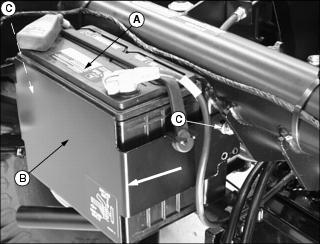
Cleaning or Replacing Battery

1. Raise attachment to service position.(See Using the Lift Cylinder Safety Support in the Safety section.)
2. Park vehicle safely. (See Parking Safely in the Safety section.)
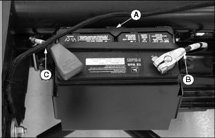
3. Disconnect rubber hold-down strap (A).
4. Remove negative (black) cable (B) from the battery first.
5. Remove positive (red) cable (C).
· Pull red terminal cover back far enough to expose terminal.
6. If battery is very dirty, remove battery.
7. Clean battery, battery terminals, cable ends,
hold-down, and battery tray with a solution of 1 part baking soda to 4 parts water. Keep solution out of battery cells.
IMPORTANT: Avoid damage! This battery comes fully charged. If the mower is not used by the Service Expiration Date indicated on the battery, charge the battery. |
NOTE: If a new battery is required, install a replacement John Deere battery or an equivalent.
8. Rinse all parts with clean water. Let dry.
10. Connect positive (red) cable (C) to battery.
11. Connect negative (black) cable (B) to battery.
12. Apply petroleum jelly on battery terminals to help prevent corrosion.
13. Install rubber hold-down strap.
Checking Battery Electrolyte Level
1. Park the vehicle safely. (See Parking Safely in the SAFETY section.)
2. Remove battery from vehicle and set it on a level surface.
3. Remove battery cell caps. Make sure cap vents are not plugged.
IMPORTANT: Avoid damage! Do not fill cells to the bottom of filler neck (A). Electrolyte can overflow when battery is charged and cause damage. |
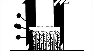
4. Electrolyte (B) should be approximately halfway between bottom of filler neck (A) and top of plates (C).
5. Add distilled water if necessary.
Using Booster Battery

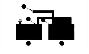
1. Connect positive (+) booster cable to booster battery (A) positive (+) post (C).
2. Connect the other end of positive (+) booster cable to the disabled vehicle battery (B) positive (+) post (D).
3. Connect negative (-) booster cable to booster battery negative (-) post (E).
4. Connect the other end (F) of negative (-) booster cable to a metal part of the disabled machine frame away from battery.
5. Start the engine of the disabled machine and run machine for several minutes.
6. Carefully disconnect the booster cables in the exact reverse order: negative cable first and then the positive cable.
Replacing Battery
NOTE: The service battery is slightly deeper and will need to have the battery bracket moved out. The battery bracket has two sets of mounting holes.
1. Remove battery (A) from bracket (B).
2. Remove hardware (C) from both sides of bracket.
3. Slide bracket (B) out to the other hole in bracket to allow the deeper service battery to fit.
4. Install hardware removed earlier and tighten.
Replacing Stoplight/Taillight Bulb
1. Park vehicle safely. (See Parking Safely in the Safety section.)
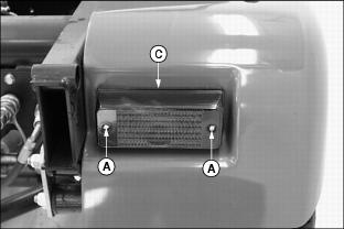
2. Remove two screws (A), attaching hardware (B) and lens (C) from the combination stoplight/taillight assembly.
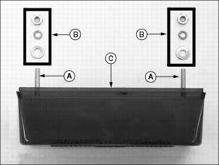
· Rotate bulb counterclockwise approximately 1/3 turn and remove from the socket.
4. Install new bulb into the socket.
· Push down top of bulb and rotate clockwise into a locked position.
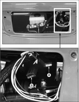
Replacing Indicator Light Bulb
1. Park vehicle safely. (See Parking Safely in the Safety section.)
NOTE: Instrument panel housing removed to illustrate photo clarity.
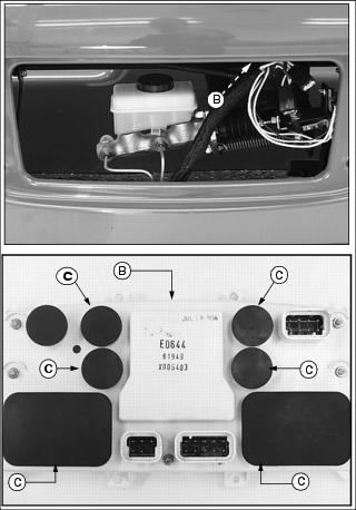
3. Locate rear of instrument panel housing (B).
4. Remove rubber plugs (C) to locate indicator bulb light assemblies.
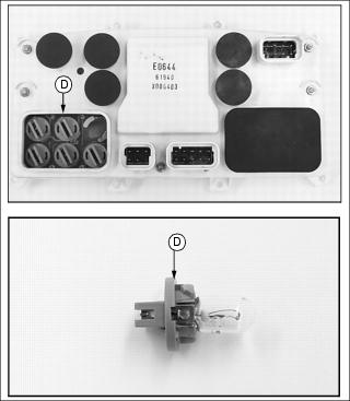
5. Remove defective bulb assembly (D) from the instrument panel housing.
· Rotate bulb assembly counterclockwise approximately 1/3 turn and remove from the housing socket.
6. Install new bulb assembly into housing socket and rotate clockwise into a locked position.
Replacing Headlight Bulb
1. Park vehicle safely. (See Parking Safely in the Safety section.)
2. Locate headlight housing under the vehicle dash.

3. Rotate bulb assembly counterclockwise approximately 1/3 turn and remove from the socket.
IMPORTANT: Avoid damage! Prevent premature failure when inspecting or replacing the headlight bulb assembly. Do not touch the assembly glass component with bare skin surfaces. |
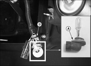
4. Disconnect wiring harness (B) from the bulb assembly.
5. Connect wiring harness to the replacement bulb assembly (A).
6. Install new headlight bulb assembly into housing socket and rotate into a locked position.
Checking and Replacing Fuses
IMPORTANT: Avoid damage! Prevent vehicle electrical circuit damage. Make sure replacement fuse is the correct size. |
1. Park vehicle safely. (See Parking Safely in the Safety section.)