![]()
Introduction
Product Identification
Safety
Operating
Console and Miscellaneous Controls
Using Fuel Shut-Off Valve (Diesel Models)
Using the Differential Lock Lever
Using the Hydraulic PTO Control Lever
Operating the 5-Speed Synchronized Transmission
Testing Safety Interlock System
Testing Seat and Park Brake Switches
Testing Auxiliary Hydraulic System Switch
Operating Vehicle Engine with Operator Off the Seat
Raising and Lowering the Cargo Box
Operating the Cargo Box Tailgate
Removing the Cargo Box Tailgate
Replacement Parts
Service Intervals
Service Engine
Service Transmission
Service - Hydraulics
Service Steering & Brakes
Service Electrical
Service Miscellaneous
Troubleshooting
Storage
Assembly
Specifications
Warranty
John Deere Quality Statement
Service Record
Copyright© Deere & Company

Operating
Daily Operating Checklist
o Check transmission oil level.
o Remove grass and debris from machine.
o Check area below machine for leaks.
Dash and Foot Controls

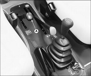
Console and Miscellaneous Controls
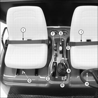
E - Hydraulic PTO Lever (Optional)
G - Passenger Seat Adjustment Lever
H - Operator Seat Adjustment Lever
Adjusting Vehicle Seats
1. Sit on the operator or passenger seat.
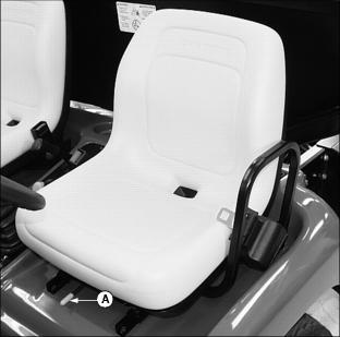
2. Pull and hold lever (A) to the left.
3. Slide seat forward or rearward to desired position.
Using Light Switch
NOTE: Using headlights for extended periods of time without engine running will discharge the battery.
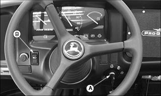
1. Turn key switch (A) to run position.
2. Push in on top of rocker switch (B) to turn lights on.
3. Turn lights off push in on bottom of rocker switch.
Using Seat Belts
· Use a seat belt when operating a vehicle with a Roll-Over Protective Structure (ROPS) or a cab. |
To connect the seat belt:
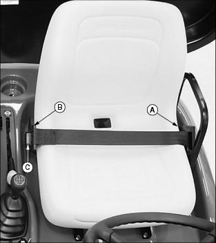
· With one continuous motion pull seat belt from retractor (A) and across hips and waist.
NOTE: If seat belt stops short of being able to insert into latch, allow belt to return into the retractor and pull again.
· Insert buckle into latch (B) on other side of seat. When properly inserted into the latch a "click" should be heard.
To disconnect the seat belt:
· Press red button (C). Allow seat belt to return to retractor.
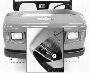
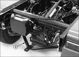
Using Fuel Shut-Off Valve (Diesel Models)
1. Locate fuel filter sediment bowl assembly on the left side of the engine.
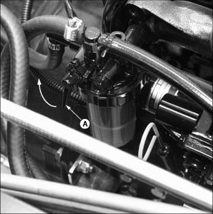
Picture Note: Fuel shut-off valve shown in the open position.
2. Rotate two-position fuel shut-off valve lever (A) to the "O" (open) position or "C" (closed) position.
"C" (Closed) position:
· When performing any type of engine service.
· During periods of extended storage.
"O" (Open) position:
· Fuel shut-off valve must be in the full open position for proper fuel delivery to the engine.
Using the Park Brake
To Lock Park Brake:
· Pull up lever (A) and latch into position.
To Unlock Park Brake:
· Push lever (A) down completely. Instrument panel indicator light must go out.
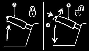
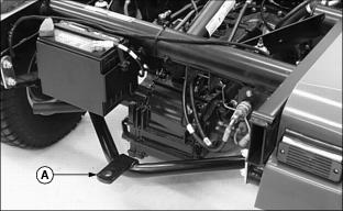
Using the Differential Lock Lever
The differential lock is used to provide better traction when the rear wheels of the vehicle start to slip. Engaging the differential lock lever will lock the left and right rear axles together and cause both rear wheels to turn at equal speeds for maximum traction.
IMPORTANT: Avoid damage! Do not engage differential lock when the vehicle is traveling at high speeds. |
NOTE: Vehicle turning radius is increased when the differential lock is engaged.
To Engage Differential Lock:
· Pull up and hold differential lock lever (A) in the raised position. Hold lever in the raised position as long as there is rear wheel slippage.
To Disengage Differential Lock:
· Lower differential lock lever (A).
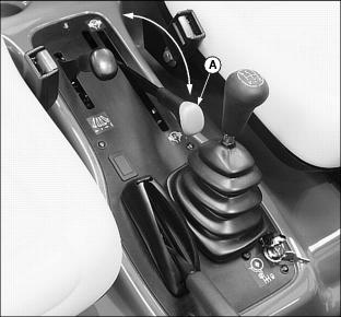
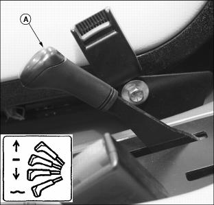
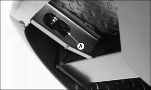
Using the Hydraulic PTO Control Lever
Perform this operational procedure with vehicles equipped with the auxiliary hydraulic kit. Engaging the hydraulic PTO lever will provide auxiliary hydraulics for attachments requiring the capability.
To Engage The Hydraulic PTO:
· Pull up lever (A) to the on position.
To Disengage The Hydraulic PTO:
· Push lever (A) down to the off position.
Using the Lift Cylinder Lever
To Raise Attachment:
2. Pull and hold back lever (A).
3. Release lever. Lever will return to the neutral position, and attachment will be held in position with the lift cylinder locked in place.
To Lower Attachment:
NOTE: An attachment can be lowered and the lift cylinder will retract with the engine running or the engine stopped.
1. Push and hold down lever until attachment is lowered or positioned as desired.
2. Release lever. Lever will return to the neutral position, and attachment will be held in position, with the lift cylinder locked in place.
NOTE: When operating the vehicle with the auxiliary hydraulic PTO engaged, it is recommended that the lift cylinder lever be held down momentarily after the attachment has been lowered. This will firmly seat the load check for the lift cylinder spool which locks the lift cylinder in position.
When operating the vehicle with a cargo box attachment having the tailgate release kit installed, the lift cylinder lever must be held down momentarily after the box has been lowered. This will lock the tailgate and eliminate tailgate rattle.
To Allow Attachment To Float:
NOTE: Float position allows the lift cylinder to move freely for use with some ground following attachments.
Placing the lift cylinder lever in the float position will cause a raised attachment to be lowered by gravity until completely down. For best control of raised loads, it is recommended that float position not be used to lower attachments.
1. Push lever (A) down, through "lower" position and with additional force, push lever down past detent to lock lever into float position.
2. Pull up lever to release float position.
3. Release lever. Lever will return to the neutral position, and attachment will be held in position, with the lift cylinder locked in place.
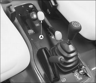
Using the 5th Gear Lockout
Picture Note: Key position shown with 5th gear locked out.
This vehicle is equipped with a keyed lock (A) for 5th gear lockout. Preventing the use of 5th gear while limiting vehicle ground speed may be advisable in certain operating conditions.
To Lockout 5th Gear:
NOTE: Lock will not operate if vehicle transmission is already in 5th gear.
1. Move gear shift lever to any position except 5th gear.
3. Install key into key switch.
IMPORTANT: Avoid damage! Do not operate the vehicle with the key left in the lock. The switch cover must be allowed to close to prevent water, sand and other contaminants from entering the lock. |
To Unlock 5th Gear:
1. Move gear shift lever to any position.
3. Install key into key switch.
Instrument Panel

F - Coolant Temperature Indicator
G - Glow Plug Circuit Indicator
(Diesel Model)
I - Battery Low Voltage Indicator
K - Engine Oil Pressure Indicator
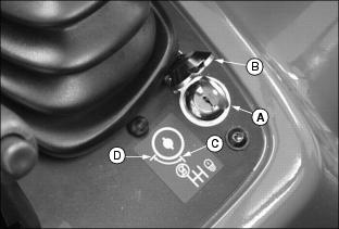
Switching Engine Speedometer
1. Disconnect the battery negative cable.
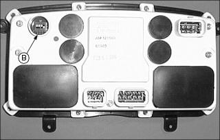
3. Locate mph/kph switch (B) on the back of instrument panel on your machine.
NOTE: The switches are set on vehicles using standard tires.
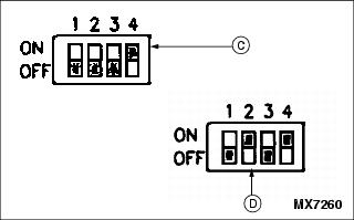
4. Toggle the switches from factory configuration for MPH (C) to KPH (D), using a screwdriver to reach each switch.
6. Connect the negative battery cable.
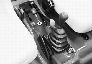
Operating the 5-Speed Synchronized Transmission
Using the Clutch Pedal
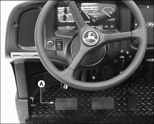
The functions of the clutch pedal (A) are:
· Connects and disconnects engine power to the transmission.
· Operates in conjunction with the gear shift lever to shift gears.
To Disengage The Clutch:
· Press the clutch pedal down completely. This will disengage the transmission from engine power.
To Engage The Clutch:
· Remove foot from clutch pedal slowly. This will engage the transmission to engine power.
Using the Gear Shift Lever
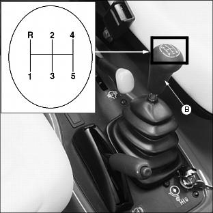
The gear shift lever (B) is located on a console to the right of the operator seat. The gear shift lever provides five forward travel speeds and one reverse speed.
Select a gear on the gear shift lever that matches desired speed and direction. First and second gears are very low and should be used when hauling heavy loads.
Forward Travel
NOTE: The gear shift lever must be in the neutral position for the engine to start.
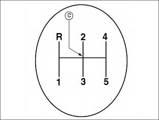
2. Move the gear shift lever to the neutral position (C) between gears "2" and "3".
3. Depress clutch pedal and start engine.
4. Move gear shift lever to a desirable starting gear.
· Vehicles with a load-first gear
· Vehicles with no load-second or third gear
6. Release clutch gradually to take up load smoothly.
· Depress clutch and shift to next gear.
Reverse Travel
3. Move gear shift lever to reverse.
Starting the Engine
3. Push hydraulic PTO lever to the off position.
4. Move the gear shift lever to the neutral position.
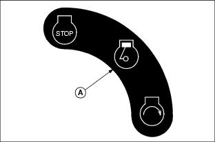
5. Turn key switch to the run position (A).
· Battery discharge indicator light should be on.
· Park brake indicator light should be on.
· Engine oil pressure indicator light should be on.
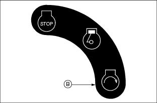
7. Turn key switch to the start position (B).
NOTE: Engine is calibrated at the factory to slow idle at 1450 RPM 50 when started.
8. When engine starts, release key switch to the run position.
· Battery discharge indicator light should go out.
· Engine oil pressure indicator light should go out.
· Park brake indicator light should go out.
Stopping the Engine
1. Release accelerator pedal and allow engine to slow idle.
2. Depress the clutch pedal and the foot brake.
3. Place gear shift lever in first or reverse gear.
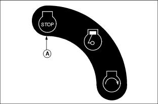
5. Turn key switch to the stop position (A).
Testing Safety Interlock System
Use the following checkout procedure to check for normal operation of machine.
If there is a malfunction during one of these procedures, Do not operate machine. See your John Deere dealer for service.
Perform these tests in a clear open area. Keep bystanders away.
Testing Seat and Park Brake Switches
3. Move gear shift lever to the neutral position.
5. With engine running at slow idle, raise off seat.
6. Engine must continue to run.
Testing Neutral Switch
3. Move the gear shift lever to the "R" (reverse) position.
4. Turn the key switch to the start position.
6. Repeat starting procedure with shift lever in each gear.
8. Move the gear shift lever to the neutral position.
9. Turn the key switch to the start position.
Testing Auxiliary Hydraulic System Switch
NOTE: Make sure no attachments are connected to the auxiliary hydraulic quick-couplers at the rear of the vehicle.
3. Move the gear shift lever to the neutral position.
4. Pull up hydraulic PTO lever to the ON position.
5. Turn the key switch to the start position.
Operating Vehicle Engine with Operator Off the Seat
· Lock park brake at all times before leaving seat. · Do not leave seat with vehicle running unless attachment function requires it. |
NOTE: During normal operating conditions, the vehicle engine should stop running when the operator raises off the seat.
To keep engine running when operator is off the seat:
1. Depress clutch and foot brake pedals to stop the vehicle.
2. Move the gear shift lever to the neutral position.
4. Slowly release clutch and foot brake pedals.
· Engine should continue to run with the operator off of the seat.
Towing the Utility Vehicle
1. Move gear shift lever to the neutral position.
2. Attach a tow line to oval slot (A) provided on either side of the main frame under the front of the vehicle.
4. Tow vehicle slowly and carefully to desired location.
Towing Loads
· Do not tow a load with this vehicle that exceeds 680 kg (1500 lb).
· Do not exceed a tongue weight of 90.7 kg (200 lb).
· Tow load at a speed slow enough to maintain control.
· Always use rear hitch point (A) provided on and approved for this utility vehicle. This is an approved hitch point, Do not modify in any way.
Transporting Utility Vehicle
1. Drive vehicle forward onto a trailer.
2. Park vehicle safely. (See Parking Safely in the Safety section.)
4. Block rear wheels with chocks or wood blocks.
5. Fasten vehicle to trailer with heavy-duty straps, chains, or cables.
· The tie downs should be attached to oval slots (A) provided on both sides of the main frame under the front of the vehicle and both sides of the hitch assembly (B) at the rear of the vehicle.
· Both front and rear straps must be directed down and outward from the vehicle.
6. When transporting the utility vehicle on a road or highway, use accessory lights and devices for adequate warning to operators of other vehicles. Check local, state, provincial, or federal laws.
Raising and Lowering the Cargo Box
2. Pull and hold back lift cylinder lever (A) to raise cargo box.
NOTE: The lift cylinder will retract and the cargo box will lower with the engine running or the engine stopped.
Pushing the lever down beyond the lower position into the detented float position will cause the box to drop more slowly then in the lower position, as the circuit is restricted to avoid a sudden drop.
3. Push and hold down lever (A) to lower cargo box.
Operating the Cargo Box Tailgate
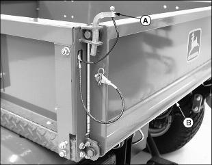
1. Pull up and remove each tailgate latch pin (A).
IMPORTANT: Avoid damage! The tailgate fully lowered can contact the rear fenders and cause structural damage. Do not operate utility vehicle with the tailgate fully lowered. |
3. Remove spring locking pin (C) and cable (D) from each drilled stud (E) to fully lower tailgate.
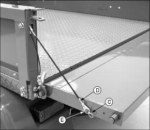
Removing the Cargo Box Tailgate
1. Close the tailgate and latch both sides.
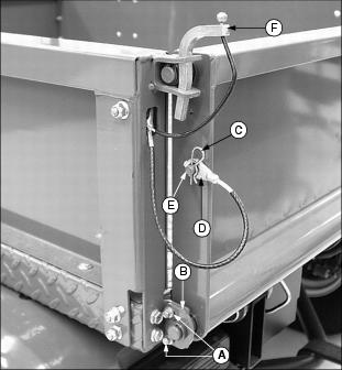
2. Remove two screws (A) and tailgate support plates (B) from each side.
3. Remove spring locking pin (C) and cable (D) from each drilled stud (E).