![]()
Introduction
Product Identification
Safety
Operating
Replacement Parts
Service Intervals
Service Engine
Engine Warranty Maintenance Statement
Changing Engine Oil and Filter
Clean Rubber Dust Unloading Valve
Cleaning Radiator Cooling Fins and Fan Shroud
Check Air Intake Hose, Hydraulic Hoses, Radiator Hoses and Clamps
Replace Fuel Filter (Gas Models)
Servicing Fuel Filter Sediment Bowl (Diesel Models)
Checking and Adjusting Alternator Belt
Replacing Alternator Belt (Gas Models)
Replacing Alternator Belt (Diesel Models)
Service Transmission
Service - Hydraulics
Service Steering & Brakes
Service Electrical
Service Miscellaneous
Troubleshooting
Storage
Assembly
Specifications
Warranty
John Deere Quality Statement
Service Record
Copyright© Deere & Company

Service Engine
Engine Warranty Maintenance Statement
Maintenance, repair, or replacement of the emission control devices and systems on this engine, which are being done at the customers expense, may be performed by any nonroad engine repair establishment or individual. Warranty repairs must be performed by an authorized John Deere dealer.
Adjusting Carburetor
NOTE: Carburetor is calibrated by the engine manufacturer and is not adjustable.
If engine is operated at altitudes above 1829 m (6,000 ft), some carburetors may require a special high altitude main jet. See your John Deere dealer.
If engine is hard to start or runs rough, check the troubleshooting section of this manual.
Possible engine surging will occur at high throttle with transmission in "N" neutral and mower engagement lever disengaged. This is a normal condition due to the emission control system.
After performing the checks in the troubleshooting section and your engine is still not performing correctly, contact your John Deere dealer.
Avoid Fumes
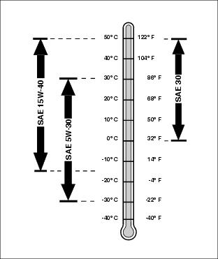
Engine Oil (Gas)
Use oil viscosity based on the expected air temperature range during the period between oil changes.
The following John Deere oils are preferred:
Other oils may be used if above John Deere oils are not available, provided they meet the following specification:
· API Service Classification SG or higher
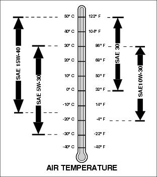
Engine Oil-Diesel Model
Use oil viscosity based on the expected air temperature range during the period between oil changes.
The following John Deere oils are preferred:
· TORQ-GARD SUPREME® (SAE 5W-30)
Other oils may be used if above John Deere oils are not available, provided they meet one of the following specifications:
· SAE 15W-40-API Service Classification CF-4 or higher.
· SAE 5W-30-API Service Classification CC or higher.
· SAE 10W-30-API Service Classification CF or higher.
· SAE 30-API Service Classification CF or higher.
Checking Engine Oil Level
NOTE: Check oil twice a day if you run engine over 4 hours in a day.
Make sure engine is cold when checking engine oil level.
1. Raise attachment to service position. (See Using the Lift Cylinder Safety Support in the Safety section.)
2. Park vehicle safely. (See Parking Safely in the Safety section.)
IMPORTANT: Avoid damage! Help prevent dirt and other contaminants from entering the oil dipstick tube location. Clean area around dipstick before removing. |
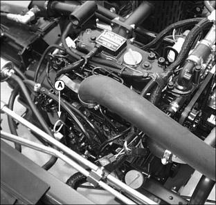
Picture Note: Diesel engine shown.
3. Remove dipstick (A). Wipe dipstick with a clean cloth.
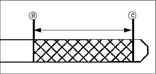
5. Remove dipstick. Check oil level on dipstick; oil level should be between levels (B) and (C) on the dipstick.
· If oil is low, add oil to bring oil level no higher than level (B) on the dipstick.
· If oil level is above level (B) on the dipstick, drain to proper level.
Changing Engine Oil and Filter
IMPORTANT: Avoid damage! Change the oil more often if the vehicle is used in extreme conditions: |
1. Run engine to warm the oil.
2. Raise attachment to service position. (See Using the Lift Cylinder Safety Support in the Safety section.)
3. Park vehicle safely. (See Parking Safely in the Safety section.)
4. Place container under the oil drain location.
Picture Note: Diesel engine shown.
5. Remove drain plug (A) located under the right side of the engine.
· Locate filter under the right side of the engine.
· Turn filter counterclockwise to remove.
7. Apply a film of clean engine oil on gasket of new filter.
· Turn filter clockwise until gasket makes contact with mounting surface. Tighten 1/2-3/4 turn after gasket contact.
9. Install oil drain plug. Do not overtighten.
NOTE: An additional oil fill cap location is located on the right side of the engine.
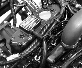
10. Remove oil fill cap (C) on top of engine.
11. Add approximately 2.1 L (2.2 qt.) of oil.
· Run engine at a slow throttle speed for approximately two minutes.
14. Check area under engine for oil leaks.
16. After approximately two minutes check engine oil level.
IMPORTANT: Avoid damage! Help prevent dirt and other contaminants from entering the oil dipstick tube location. Clean area around dipstick before removing. |
17. Remove dipstick. Wipe with a clean cloth.
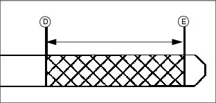
19. Remove dipstick. Check oil level on dipstick; oil level should be between levels (D) and (E) on the dipstick.
· If oil is low, add oil to bring oil level no higher than level (D) on the dipstick.
· If oil level is above level (D) on the dipstick, drain to proper level.
Checking Spark Plugs
1. Raise attachment to service position. (See Using the Lift Cylinder Safety Support in the Safety section.)
2. Park vehicle safely. (See Parking Safely in the Safety section.)
3. Clean area around each spark plug.
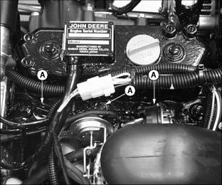
4. Disconnect the spark plug wire (A) from each plug.
5. Remove and inspect spark plugs:
· Clean each plug and check for damage, replace if necessary.
· If plugs are in good condition, check gap.
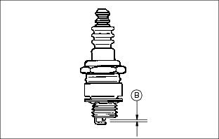
6. Check and adjust spark plug gap (B) to 0.76 mm (0.030 in.).
· Tighten to 20 N·m (15 lb-ft).
8. Install each spark plug wire.
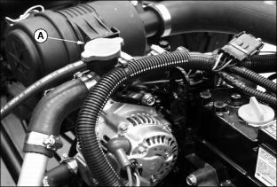
Clean Rubber Dust Unloading Valve
IMPORTANT: Avoid damage! Never operate engine without air cleaner element and rubber dust unloading valve installed. |
1. Raise attachment to service position. (See Using the Lift Cylinder Safety Support in the Safety section.)
2. Park vehicle safely. (See Parking Safely in the Safety section.)
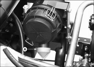
3. Remove dust unloading valve (A) and clean. Replace if damaged.
4. Install dust unloading valve.
Cleaning Air Intake Screen
1. Raise attachment to service position. (See Using the Lift Cylinder Safety Support in the Safety section.)
2. Park vehicle safely. (See Parking Safely in the Safety section.)
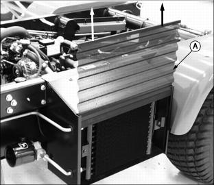
3. Lift air intake screen (A) from position in front of the engine radiator.
4. Clean screen with a brush or compressed air.
Cleaning Radiator Cooling Fins and Fan Shroud
IMPORTANT: Avoid damage! Dirty cooling fins and intake screens can cause engine overheating. The radiator cooling fins and fan shroud must be clean. |
1. Raise attachment to service position. (See Using the Lift Cylinder Safety Support in the Safety section.)
2. Park vehicle safely. (See Parking Safely in the Safety section.)
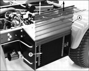
3. Remove air intake screen (A).
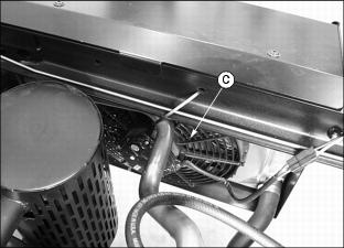
4. Remove dirt and debris from the radiator cooling fins (B) and fan shroud (C) using compressed air or water.
5. Check radiator fins for damage.
Servicing Air Cleaner Element
Checking Air Cleaner Element
1. Raise attachment to service position. (See Using the Lift Cylinder Safety Support in the Safety section.)
2. Park vehicle safely. (See Parking Safely in the Safety section.)
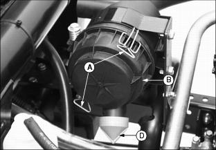
3. Release latches (A) and remove air cleaner canister cover (B).
4. Visually inspect each element before removing. Replace element only if damaged or very dirty.
Replacing Primary Air Filter Element
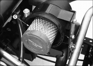
1. Remove and discard primary element (C). Replace with a new primary filter element.
2. Install air cleaner canister cover (B).
· Check instruction molded into canister cover for proper installation.
· Rubber dust unloading valve (D) should be pointed downward when the cover is properly installed.
Replacing Secondary Air Filter Element
1. Remove air cleaner canister cover.
2. Remove primary air filter element.
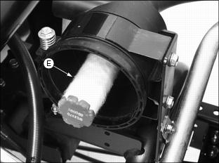
3. Remove and discard secondary air filter element (E). Replace with a new secondary air filter element.
4. Install primary air filter element.
5. Replace air cleaner canister cover.
Check Air Intake Hose, Hydraulic Hoses, Radiator Hoses and Clamps
1. Raise attachment to service position. (See Using the Lift Cylinder Safety Support in the Safety section.)
2. Park vehicle safely. (See Parking Safely in the Safety section.)
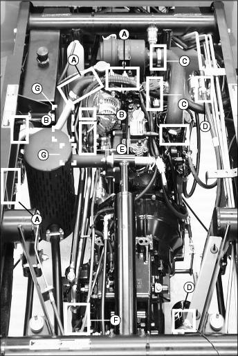
A - Upper Radiator Hoses (6 Clamps)
B - Lower Radiator Hoses (4 Clamps)
C - Air Intake Hose (2 Clamps)
E - Hydraulic Suction Manifold (4 Clamps)
3. Check hoses for leaking or damage and adjustable clamps for tightness. Replace if necessary.
Service Cooling System Safely
Recommended Engine Coolant
The following John Deere coolants are preferred:
· COOL-GARD PRE-DILUTED SUMMER COOLANT (TY16036).
· COOL-GARD CONCENTRATED SUMMER COOLANT (TY16034).
If neither of the recommended coolants is available, use a glycol base coolant that meets the following specification:
Check container label before using to be sure it has the appropriate specifications for your machine. Use coolant with conditioner or add conditioner to coolant before using.
If using concentrate, mix approximately 50 percent antifreeze with 50 percent distilled or deionized water before adding to cooling system. This mixture will provide freeze protection to -37 degrees C (-34 degrees F).
Certain geographical areas may require lower temperature protection. See the label on your antifreeze container or consult your John Deere dealer to obtain the latest information and recommendations.
Checking Coolant Level
1. Raise attachment to service position. (See Using the Lift Cylinder Safety Support in the Safety section.)
2. Park vehicle safely. (See Parking Safely in the Safety section.)

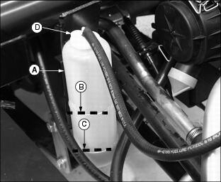
3. Check recovery bottle (A) coolant level:
· If engine is warm, coolant level should be between the "FULL" line (B) and the "LOW" line (C).
· If engine is cold, coolant level should be at the "LOW" line (C) on the recovery bottle.
4. Remove recovery bottle cap (D) to add coolant.
5. If coolant is low, add specified ratio of antifreeze and water.
6. Install and tighten recovery bottle cap.
7. Clean debris from the air intake screen, fan shroud, radiator cooling fins and auxiliary oil cooler coils.
8. Check condition of coolant system hoses and clamps. Check for leaks or loose connections.
Draining Cooling System
|
· Do not operate engine without coolant. · Do not pour coolant into the radiator when the engine is hot. |
1. Raise attachment to service position. (See Using the Lift Cylinder Safety Support in the Safety section.)
2. Park vehicle safely. (See Parking Safely in the Safety section.)
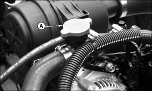
3. Slowly open radiator cap (A) to the first stop to release all pressure.
4. Close radiator cap tightly.
5. Open radiator petcock (B). Drain coolant into a pan.
6. When coolant drains from the recovery bottle, remove radiator cap.
7. After all coolant has drained, close radiator petcock.
Flushing Cooling System
Turn radiator cap using a thick rag or glove to protect your hand. |
1. Fill cooling system with clean water and John Deere Cooling System Cleaner, or John Deere Cooling System Quick Flush or an equivalent. Follow directions on the can.
2. Install and tighten radiator cap (A).
3. Start and run engine until it reaches operating temperature.
· Drain cooling system immediately before rust and dirt settle.
Filling Cooling System
NOTE: John Deere COOL-GARD coolant is recommended when adding coolant to the cooling system.
Follow the directions on the container for correct mixture ratio.
1. Fill cooling system with approximately 3.8 L (4.1 qt.) of coolant.
· Certain geographical areas may require protection from lower temperatures. See the label on your antifreeze container or consult your John Deere distributor to obtain the latest information and recommendations.
· John Deere Cooling System Sealer or its equivalent may be added to the radiator to seal leaks. Do not use any other additives in the cooling system.
2. Install and tighten radiator cap.
3. Run engine until it reaches operating temperature.
5. Check recovery bottle (A) coolant level:
· If engine is warm, coolant level should be between the "FULL" line (B) and the "LOW" line (C).
· If engine is cold, coolant level should be at the "LOW" line (C) on the recovery bottle.
6. Remove cap (D) from recovery bottle to add coolant if necessary.
7. Check condition of coolant system hoses and clamps.
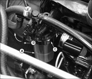
Replace Fuel Filter (Gas Models)
NOTE: Change filter when fuel is low.
1. Raise attachment to service position. (See Using the Lift Cylinder Safety Support in the Safety section.)
2. Park vehicle safely. (See Parking Safely in the Safety section.)
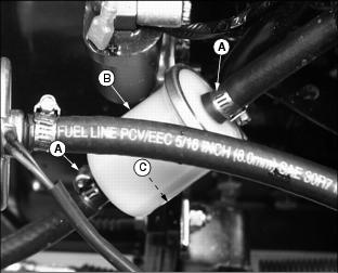
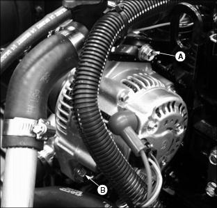
3. Slide hose clamps (A) away from filter (B) located on the right side of the engine.
4. Disconnect hoses from filter.
NOTE: When installing a new fuel filter, make sure the filter arrow (C) is pointed in the direction of the fuel flow.
6. Connect hoses to new filter.
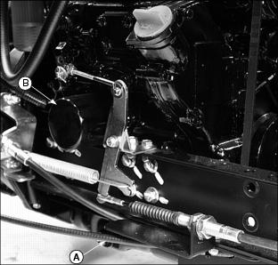
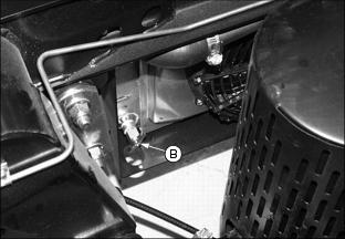
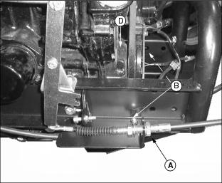
Servicing Fuel Filter Sediment Bowl (Diesel Models)
Checking
1. Raise attachment to service position. (See Using the Lift Cylinder Safety Support in the Safety section.)
2. Park vehicle safely. (See Parking Safely in the Safety section.)
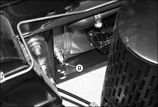
3. Visually check for water and deposits in the sediment bowl (A).
4. If necessary, clean bowl and replace filter.
Cleaning and Replacing
1. Close fuel shut-off valve (B).
2. Turn collar (C) to remove bowl and filter. Discard filter.
4. Install new filter and bowl.
Checking and Adjusting Alternator Belt
Check Belt Tension
1. Raise attachment to service position. (See Using the Lift Cylinder Safety Support in the Safety section.)
2. Park vehicle safely. (See Parking Safely in the Safety section.)
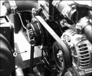
· Inspect belt for excessive wear, damage or stretching while in position on the sheaves.
· Apply thumb pressure to the belt approximately halfway between the sheaves. Belt should deflect inward approximately 10 mm (3/8 in.).
Adjusting Belt Tension
1. Loosen adjustment bolt (B).
2. Loosen alternator mounting bolt (C).
3. Apply outward pressure to the alternator housing.
4. Tighten alternator adjustment bolt (B) and mounting bolt (C).
· Apply thumb pressure to the belt approximately halfway between the sheaves. Belt should deflect inward approximately 10 mm (3/8 in.).
Replacing Alternator Belt (Gas Models)
1. Raise attachment to service position.(See Using the Lift Cylinder Safety Support in the Safety section.)
2. Park vehicle safely. (See Parking Safely in the Safety section.)
3. Remove skid plate (A) mounted under the vehicle in front of the engine.
· Remove two hex bolts (B) and flanged lock nuts and retain for use later.
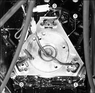
5. Loosen alternator adjustment bolt (E).
6. Remove alternator mounting bolt (F).
7. Apply inward pressure to the alternator housing.
8. Remove worn belt from the alternator sheave and both engine sheaves.
10. Install alternator mounting bolt (F). DO NOT tighten.
11. Apply outward pressure to the alternator housing.
12. Tighten adjustment bolt (E) and mounting bolt (F).
· Apply thumb pressure to the belt approximately halfway between the sheaves. Belt should deflect inward approximately 10 mm (3/8 in.).
14. Install pulser bracket with four cap screws.
NOTE: Install bolts from inside to the outside of the skid plate.
15. Install skid plate with two hex bolts and flanged lock nuts removed earlier.
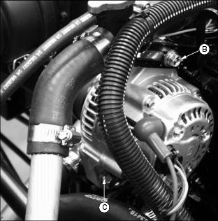
Replacing Alternator Belt (Diesel Models)
1. Raise attachment to service position. (See Using the Lift Cylinder Safety Support in the Safety section.)
2. Park vehicle safely. (See Parking Safely in the Safety section.)
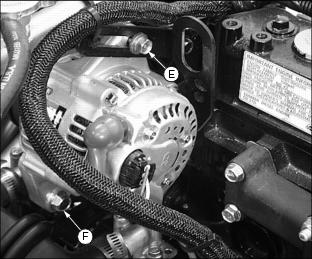
3. Loosen adjustment bolt (A).
4. Remove alternator mounting bolt (B).
5. Apply inward pressure to the alternator housing.
6. Remove worn belt from the alternator sheave and both engine sheaves.
8. Install alternator mounting bolt (B). DO NOT tighten.
9. Apply outward pressure to the alternator housing.
10. Tighten alternator adjustment bolt (A) and mounting bolt (B).
· Apply thumb pressure to the belt approximately halfway between the sheaves. Belt should deflect inward approximately 10 mm (3/8 in.).