Introduction
Safety Signs
Controls
Operating Machine
Operating Mower
Lawn Care
Replacement Parts
Service Machine Safely
Service Interval Chart
Service Engine
Service Transmission
Service Steering & Brakes
Lubricating The Steering Spindles And Ball Joints
Lubricating The Transmission Control Arm
Service Mower
Service Electrical
Service Miscellaneous
Removing Mower
Installing Mower
Troubleshooting
Storing Machine
Assembly
Specifications
Warranty
John Deere Service Literature
QUALITY DOESN'T END WHEN YOU INVEST IN A DEERE

Service Steering & Brakes
Grease
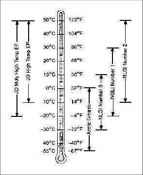
Use grease based on the expected air temperature range during the service interval.
The following greases are preferred:
· John Deere MOLY HIGH TEMPERATURE EP GREASE.
· John Deere HIGH TEMPERATURE EP GREASE.
Other greases may be used if they meet one of the following:
· SAE Multipurpose EP Grease with a maximum 5 percent molybdenum disulfide.
· Greases meeting Military Specification MIL-G-10924F may be used as arctic grease.
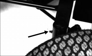
Lubricating The Steering Spindles And Ball Joints
1. Lubricate the left and right rear axle spindle. (The left rear axle spindle is shown.)
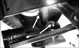
2. Lubricate ball joint and center spindle.
Use John Deere Multipurpose Grease or equivalent.
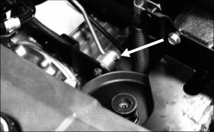
Lubricating The Transmission Control Arm
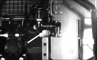
1. Lift the seat to the second position.
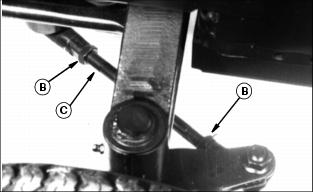
Lubricating The Pedal Pivot
NOTE: The picture is a mirrored image.
Use John Deere Multipurpose Grease or equivalent.
Adjusting The Brake
1. Park the Front Mower on a hard, level surface.
2. STOP the engine. UNLOCK the park brake.
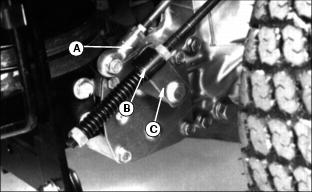
3. Remove the cotter pin (A) from the back of the trunnion (B).
4. Remove the trunnion from the brake arm (C).
5. Turn the brake arm clockwise until you feel resistance. Hold the arm there.
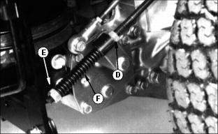
6. Turn the jam nuts (D) on the rod until the trunnion fits into the brake arm. Your Front Mower will have two jam nuts.
7. Install the cotter pin in the trunnion.
8. Tighten the nut (E) until the spring (F) is 75 mm (3 in.) long.
Checking The Toe-In
1. Park the Front Mower on a hard, level surface.
2. Stop the engine. Lock the park brake.
3. Turn the left, rear wheel as far as it will go to the left.
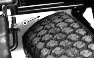
4. Check the clearance (A) between the left tire and the rod. Clearance should be 6-13 mm (1/4-1/2 in).
5. If not, adjust the left tie-rod.
· Turn the tie-rod (C) until clearance in step 4 is correct.
· Flatten washer to nut and tie-rod flats.
6. Turn the steering wheel so the rear wheels are in the straight-ahead position.
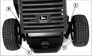
7. Measure distance from D to E:
· At the front of the rear wheels.
· At the widest part of the tires.
8. Measure distance from F to G:
· At the rear of the rear wheels.
· At the widest part of the tires.
9. Distance (D) to (E) should be 3 mm (1/8 in.) less than distance (F) and (G).
10. If not, adjust the right-hand tie rod length until the toe-in is correct. (The left-hand tie rod is not changed). See step 5.

