Introduction
Safety Signs
Controls
Operating Machine
Operating Mower
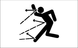
Avoid Injury From Contacting Blades
Adjusting The Cutting Height And Gauge Wheel
Leveling The Mower Side-To-Side
Leveling The Mower Front-To-Rear
Adjusting Mower Level Front-To-Rear
Engaging And Disengaging The Mower
Using The Differential Lock Pedal
Using The Weight Transfer Control
Lawn Care
Replacement Parts
Service Machine Safely
Service Interval Chart
Service Engine
Service Transmission
Service Steering & Brakes
Service Mower
Service Electrical
Service Miscellaneous
Removing Mower
Installing Mower
Troubleshooting
Storing Machine
Assembly
Specifications
Warranty
John Deere Service Literature
QUALITY DOESN'T END WHEN YOU INVEST IN A DEERE

Operating Mower
Check Ground Conditions
· Clear mowing area of objects that might be thrown. Keep people and pets out of mowing area.
· Study mowing area. Set up safe mowing pattern. Do not mow under conditions where traction or stability is doubtful.
· First, test drive area with PTO switch DISENGAGED and mower lowered. Slow down when you travel over rough ground.
Avoid Injury From Contacting Blades
Before you dismount to unplug or adjust mower:
· DISENGAGE PTO switch to stop mower blades.
· Wait for mower blades to STOP.
· Keep hands, feet and clothing away from mower deck when engine is running.
· DISENGAGE PTO switch to stop mower blades when you are not using mower.
Adjusting The Cutting Height And Gauge Wheel
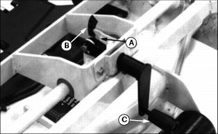
NOTE: The pointer (A) does not show the cutting height on the decal (B). The numbers 1-4 are for reference only.
1. Turn the crank (C) to put the mower at the desired cutting height-from 25-100 mm (1-4 in). One turn of the crank will raise or lower the mower approximately 6 mm (1/4 in). Leave the crank at the bottom of a turn.
2. Cut a short strip of grass. For best results, measure the height of the grass at several places in the strip.
3. When the mower is set at the desired cutting height, note the pointer number on the decal. Use this number as a reference to set the cutting height in the future.
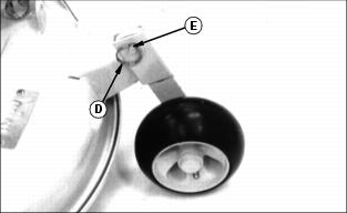
4. Remove the ring (D) and drilled pin (E) from the wheel arm.
· For normal operation: Adjust the wheel to 6 mm (1/4 in.) above the ground.
· For rough or uneven ground: If scalping is a problem, try running the wheel on the ground.
6. Install the drilled pin and the ring.
Checking Blade Stop Time
1. Run engine at HALF-THROTTLE (A).
3. Move throttle lever to FAST (r) position.
4. Push PTO knob down to OFF and begin timing.
5. Watch mower drive belt. Note time when belt stops to get blade stop time.
6. If belt stop time is more than 6 seconds, adjust PTO clutch.
Leveling The Mower Side-To-Side
1. Park the Front Mower on a hard, level surface.
· Front Mower drive tires: 60 kPa (8 psi)
· Front Mower rear tires: 100 kPa (15 psi)
· Mower tires: 310 kPa (45 psi)
3. Use the crank to put the mower at the desired cutting height.
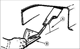
5. Lift the mower chute. Measure from the right blade tip to the floor: Dimension (A).
NOTE: Use a short ruler or leveling gauge (B) for measuring.
6. Measure from the left blade tip to the floor: Dimension (A).
7. Dimension (A) must be same on each side 3 mm (1/8 in). If not, adjust the level.
Adjusting Mower Level
1. Raise and block one side of the mower-about 150 mm (6 in).
3. Remove the wheel from the mower.
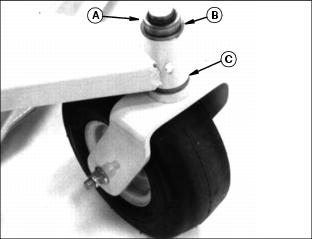
4. Put the top washer(s) (B) in the bottom position (C) to raise one side of the mower, OR put the bottom washer(s) in the top position to lower the mower. Keep the thin thrust washer between washer(s) (C) and the bottom bushing.
Leveling The Mower Front-To-Rear
1. Park the Front Mower on a hard, level surface.
· Front Mower drive tires: 60 kPa (8 psi)
· Front Mower rear tires: 100 kPa (15 psi)
· Mower tires: 310 kPa (45 psi)
3. Turn the right blade to point straight ahead.
4. Measure from the right, front blade tip to the floor: Dimension (A).
5. Turn the right blade 180 degrees. Measure from the right, rear blade tip to the floor.
6. Dimension (A) at the rear of the blade should be 3-6 mm (1/8-1/4 in.) more than dimension (A) at the front of the blade. If not, adjust the level.
Adjusting Mower Level Front-To-Rear
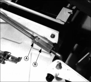
2. Turn the turnbuckle (B) to raise or lower the rear of the mower.
3. When the adjustment is correct, tighten the nut (A).
4. Repeat Steps 3-9 on the left side of the mower.
Engaging And Disengaging The Mower
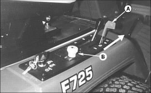
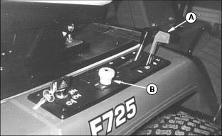
IMPORTANT: Avoid damage! To help prevent damage to the PTO clutch, ENGAGE the mower at ONE-HALF throttle. |
· Put the throttle lever (A) in the ONE-HALF speed position.
· Pull the PTO knob (B) up to the ON position.
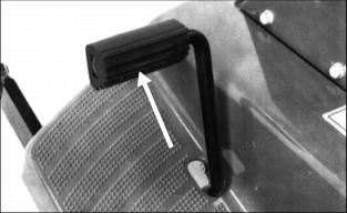
Using The Differential Lock Pedal
Push the pedal down to help improve traction on slopes and in slippery places.
· The differential will stay LOCKED as long as you hold the pedal down OR as long as the wheel slip is unequal.
To UNLOCK the differential: RELEASE the pedal.
Using The Weight Transfer Control
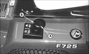
Use the weight transfer control (A) to help improve traction.
NOTE: When you transfer some of the mower weight to the drive wheels, the mower will not follow the ground contour as well.
To help transfer some of the mower weight to the drive wheels:
· Check the position of the notch (B) with the plus (+) and minus (-) signs on the base.
· Turn the knob clockwise toward the plus (+) sign to help add weight to the drive wheels.
· Turn the knob counterclockwise toward the minus (-) sign to transfer less weight to the drive wheels.
To LIFT the mower when you come to an obstacle:
· PULL THE KNOB UP: The mower will stay UP as long as you hold the knob up.
· RELEASE THE KNOB: The knob and the mower will go back down.

