![]()
Sabre Yard and Garden Tractors
Introduction
Product Identification
Safety
Operating
Replacement Parts
Service Interval Chart
Service Lubrication
Service Engine
Service Transmission
Service Mower
Avoid Injury From Contacting Blades
Adjusting Mower Drive Belt Tension
Service Electrical
Service Miscellaneous
Troubleshooting
Storing Machine
Assembly
Specifications
Warranty
Sabre by John Deere Quality Statement
Service Record
Copyright© Deere & Company

Service Mower
Avoid Injury From Contacting Blades

Removing Mower
1. STOP engine, LOCK park brake, push PTO switch down to DISENGAGE, turn key to the OFF position, and remove key.
2. Raise mower to TRANSPORT (upper) position using lift lever.
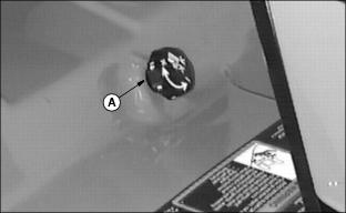
3. Set cutting height knob (A) to 25 mm (1 in.).
4. Put wood blocks under each side of mower.
5. Lower mower to MOWING (lower) position, bring deck down onto blocks.

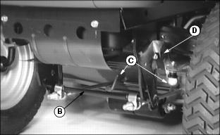
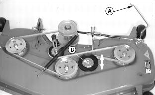
Picture Note: 54-Inch Deck Shown
6. Release drive belt tension rod (B) from bracket (C).
7. Remove belt from engine drive sheave (D).
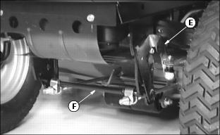
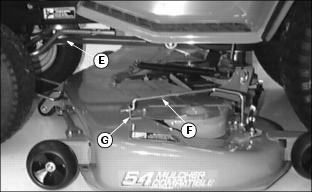
8. Pull out and push down on lever (E) to release front lift rod assembly (F) and remove from front of deck.
Picture Note: 54-Inch Deck Shown
9. Disconnect draft arms, one on each side, by pulling spring loaded J-pins (G) out.
10. Put mower lift lever in the TRANSPORT (upper) position.
11. Slide mower out from under the tractor.
Installing Mower
1. STOP engine, LOCK park brake, push PTO switch down to DISENGAGE, turn key to the OFF position, and remove key.
2. Raise mower lift lever to TRANSPORT (upper) position.
3. Slide mower under the tractor and line up mower lift brackets with rear draft arms.
4. Put wood blocks under each side of mower.
5. Put mower lift lever in the MOWING (lower) position.
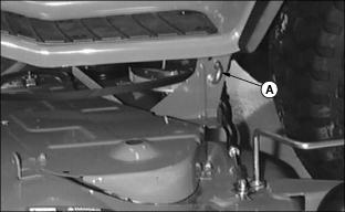
Picture Note: 54-Inch Deck Shown
6. Install rear draft arms, one on each side of tractor, to mower lift brackets with spring loaded J-pins (A).
7. Put front lift rod assembly (B) in slotted brackets (C) on mower deck and install the front lift rod assembly to the front of the tractor frame.
8. Push up on lever (D) and lock into tractor frame.
Picture Note: 54-Inch Deck Shown
9. Put mower drive belt (E) on engine drive sheave.
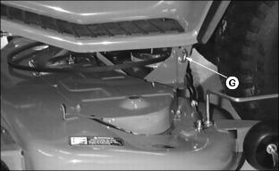
10. Push drive belt tension rod (F) into bracket (G).
11. Raise mower lift lever to TRANSPORT (upper) position.
12. Remove wood blocks from both sides of mower.
Replacing Mower Drive Belt
1. STOP engine, LOCK park brake, push PTO switch down to DISENGAGE, turn key to the OFF position, and remove key.
2. Remove mower deck. (See Removing Mower in Removing Mower section.)
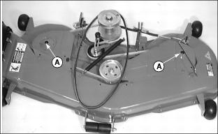
Picture Note: 54-Inch Deck Shown
3. Remove three cap screws and belt shields (A).
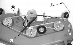
Picture Note: 48-Inch Deck Shown
4. Put drive belt tension rod (B) in the released position as shown and disconnect idler spring (C).
6. Clean upper mower deck and sheaves.
7. Inspect belt for wear or damage; replace as necessary.
8. Install belt (D) on mower deck as shown.
10. Install two belt shields and fasten with three cap screws.
11. Install mower deck. (See Installing Mower in Installing Mower section.)
Adjusting Mower Drive Belt Tension
1. STOP engine, LOCK park brake, push PTO switch down to DISENGAGE, turn key to the OFF position, and remove key.
3. Remove three cap screws and belt shields.
Picture Note: 48-Inch Deck Shown
4. Leave drive belt tension rod (A) in the open position.
5. Loosen nut (B) on flat idler.
6. Slide flat idler forward or back to get the desired belt tightness and tighten flat idler nut.
7. Install two belt shields and fasten with three cap screws.
Servicing Mower Blades
1. Raise mower deck to gain access to mower blades. If necessary, remove mower deck.
2. Using a wooden block, prevent mower blades from spinning.
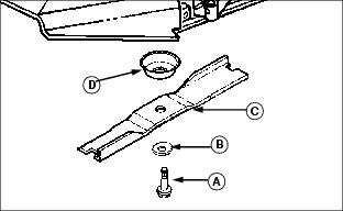
4. Remove cap screw (A), round blade washer (B), blade (C) and deflector cup (D).
5. Inspect blades; sharpen/balance or replace as necessary.
1. Lightly lubricate cap screw threads with a general purpose grease or oil. This lubrication is to prevent rusting and seizing.
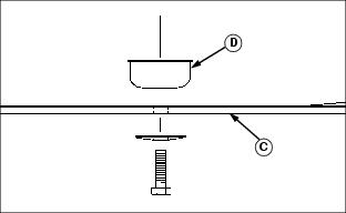
2. Install deflector cup (D) on spindle.
3. Position mower blade (C) with the cutting edge towards the ground onto the mower spindle.
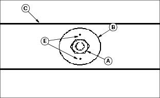
4. Install blade washers (B) and make sure 2 index marks (E) are visible when installed.
5. Install and tighten cap screw (A) by hand until mower blade is in full contact (fully seated) with spindle.
6. With mower blade blocked, to prevent spinning, tighten cap screw (A) to 84 N·m (62 lb.-ft.).
Sharpening Blades
1. Sharpen blades with grinder, hand file or electric blade sharpener.
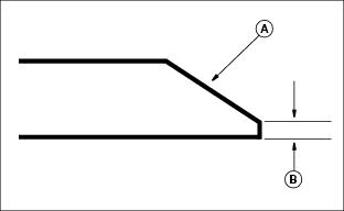
2. Keep original bevel (A) when you grind.
3. Blade should have 0.40 mm (1/64 in.) cutting edge (B).
Balancing Blades
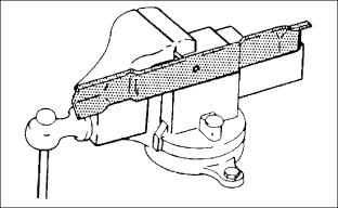
2. Put blade on nail in vise or on vertical wall stud. Turn blade to horizontal position.