![]()
Sabre Yard and Garden Tractors
Introduction
Product Identification
Safety
Operating
Adjusting Mower Level (Side-to-Side)
Adjusting Mower Level (Front-to-Rear)
Checking Indicator Lights and Hour Meter
Using and Stopping Automatic Transmission
Using and Stopping Gear Transmission
Using Lift Lever to Raise and Lower Mower
Dismounting to Inspect or Unplug Mower or Optional Bagger
Using Reverse Implement Option
Avoid Damage to Plastic and Painted Surfaces
Preparing Tractor for Installing Chains on Tires
Replacement Parts
Service Interval Chart
Service Lubrication
Service Engine
Service Transmission
Service Mower
Service Electrical
Service Miscellaneous
Troubleshooting
Storing Machine
Assembly
Specifications
Warranty
Sabre by John Deere Quality Statement
Service Record
Copyright© Deere & Company

Operating
Daily Operating Checklist
· Remove grass and debris from machine.
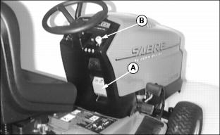
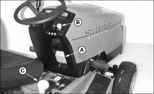
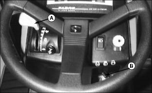
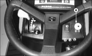
Operator Station Controls
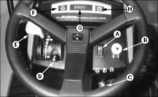
F - Engine Oil Pressure Light (21, 23, and 25 HP models only)
G - Hour Meter (21, 23, and 25 HP models only)
Picture Note: Automatic Models
A - Clutch Pedal (Gear model only)

A - Cut Height Adjustment Lever
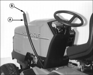
Adjusting Seat
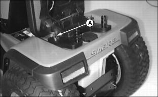
1. Tip seat forward and loosen two knobs (A) to slide seat assembly forward or rearward to most comfortable OPERATOR position.
2. Tighten knobs after adjustment to keep seat in place.
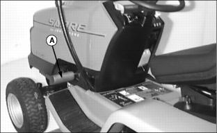
Adjusting Cutting Height
IMPORTANT: Avoid damage! Lift lever must be in TRANSPORT (upper) position before turning cutting height knob. |
NOTE: Adjust mower deck gage wheels after you change cutting height. (See Adjusting Mower Gage Wheels in this section.)
Cutting height can be adjusted from approximately 25-100 mm (1-4 in).
When lift lever is in TRANSPORT (upper) position (lift lever all the way back), cutting height is approximately 100 mm (4 in).

Knob (A) has cutting height identification numbers embossed in it. To change or attain cutting height desired:
· Pull lift lever all the way back to TRANSPORT (upper) position.
· Turn cutting height knob (A) to desired cutting height position. Mower will be at this cutting height each time you lower it.
Adjusting Mower Gage Wheels
IMPORTANT: Avoid damage! Mower gage wheels must not ride on ground to support mower weight. Adjust gage wheels each time you change cutting height. |
1. Check tractor tire pressure. Inflate tires to the correct pressure. (See Checking Tire Pressure in Service - Miscellaneous section.)
2. Raise mower lift lever to TRANSPORT (upper) position and adjust cutting height. (See Adjusting Cutting Height in this section.)
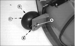
3. Remove bolt (A), bushing (B), washer (C), and tighten with nut (D).
4. Move mower gage wheels, one on each side, to one of four holes for desired position.
5. Install bolt and tighten with nut.
6. Move lift lever forward to MOWING (lower) position.
7. Bottom of gage wheels should be approximately 6-13 mm (1/4-1/2 in) from the ground when properly adjusted.
Adjusting Mower Level (Side-to-Side)
Be careful of sharp edges on mower blades. Always wear gloves when handling mower blades. |
NOTE: A deck leveling gauge (Part Number TY15272) to aid in deck leveling may be obtained through your local SABRE Service Center at a nominal cost.
1. Park tractor on a hard, level surface.
2. Stop engine and remove key.
3. CHECK: Tire pressures must be correct. (See Checking Tire Pressure in Service - Miscellaneous section.)
4. Adjust cutting height to 50 mm (2 in). (See Adjusting Cutting Height in this section.)
NOTE: Mower gage wheels should not contact the ground.
5. Put mower lift lever in MOWING (lower) position.
6. Turn left blade by hand parallel to tractor axle. Hold drive belt and turn right blade parallel to axle.
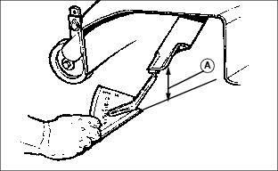
7. Measure from each outside blade tip (A) to the level surface. The difference between measurements must not be more than 3 mm (1/8 in).
NOTE: Adjustable lift links are on both sides of mower. Cutting height can closely match knob setting by using adjustment on both sides. DO NOT adjust deck too high or it will not lock in transport (upper) position.
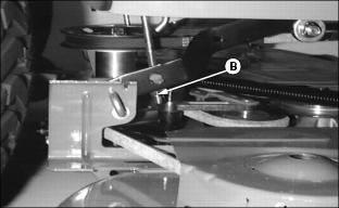
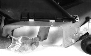
8. Turn nut (B), (right side shown): Clockwise to RAISE right side of mower and counterclockwise to LOWER right side of mower.
9. Check side-to-side measurements and readjust if necessary.
Adjusting Mower Level (Front-to-Rear)
Be careful of sharp edges on mower blades. Always wear gloves when handling mower blades. |
NOTE: Mower gage wheels should not contact the ground during leveling.
1. Park tractor on a hard, level surface.
2. Stop engine and remove key.
3. CHECK: Tire pressure must be correct. (See Checking Tire Pressure in Service - Miscellaneous section.)
4. Pull lift lever all the way back to TRANSPORT (upper) position.
5. Turn mower depth control knob (A) to adjust cutting height to 50 mm (2 in).
6. Move lift lever forward to MOWING (lower) position.
7. Turn left blade so blade tip points straight forward.
8. Hold drive belt and turn right blade straight forward.
9. Measure from the front of each blade tip to the level surface. The front blade tips must be 6-9 mm (1/4-3/8 in.) lower than rear blade tips or blades will cut grass twice and tips will turn brown.
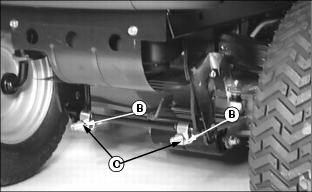
10. Loosen two rear nuts (B) on front lift rod assembly and turn two front nuts (C) clockwise to RAISE front of mower deck or counterclockwise to LOWER front of mower deck.
11. Tighten rear nuts (B) after adjustment is completed.
12. Check front-to-rear deck measurements and readjust if necessary.
Testing Safety Systems
NOTE: Your Garden Tractor is equipped with a ELECTRONIC SAFETY INTERLOCK. Engine will not start unless: PTO switch is DISENGAGED and brake pedal is depressed OR parking brake is set.
Use the following checkout procedure to check for normal operation of tractor.
If there is a malfunction during one of these procedures, DO NOT operate tractor. (See your Sabre Service Center for service.)
Perform these tests in a clear open area. Keep bystanders away.
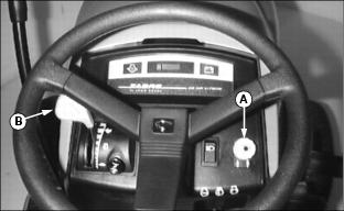
Test 1
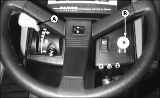
Check operation of indicator lights:
· 21, 23 and 25 HP Only, Engine Oil Pressure Light (A) on MUST light.
· Battery Discharge Light (B) will momentarily light, this is indicates the system is functioning properly. If the light remains on start engine and move throttle to high idle, the light should go out.
NOTE: The battery discharge light may remain on for several minutes while the battery is being charged.
3. If one indicator does not light, see Replacing Indicator Light Bulb in Service - Electrical section.
4. If new indicator bulb does not light or no indicators work, see your Sabre Service Center for service.
Test 2
3. Push PTO switch (B) down to DISENGAGE.
5. Engine MUST NOT start. If engine starts, there is a problem with your safety interlock circuit.
Test 3

3. Pull PTO switch (B) up to ENGAGE.
5. Engine MUST NOT start. If engine starts, there is a problem with your safety interlock circuit.
Test 4
3. Push PTO switch (A) down to DISENGAGE.
4. Start engine and move throttle lever (B) to HALF-SPEECD position.
5. Pull PTO switch (A) up to ENGAGE.
6. Move throttle lever (B) to FAST speed position.
7. Raise up off of seat. DO NOT get off tractor.
8. Engine MUST stop. If engine does not stop, there is a problem with your safety interlock circuit.
Test 5
3. Push PTO switch (A) down to DISENGAGE.
4. Release forward travel pedal (B) to N (NEUTRAL) position.
5. Start engine and move throttle lever (C) to FAST speed position.
7. Raise up off of seat. DO NOT get off tractor.
8. Engine MUST stop. If engine does not stop, there is a problem with your safety interlock circuit.
Test 6

3. Push PTO switch (A) down to DISENGAGE.
4. Start engine and move throttle lever (B) to FAST speed position.
5. Raise up off of seat. DO NOT get off tractor.
6. Engine MUST remain running. If engine does stop, there is a problem with your safety interlock circuit.
Test 7

2. Pull out free-wheeling lever.
3. Try to push machine manually.
4. Park brake MUST prevent machine from moving. If machine moves, parking brake needs to be adjusted.
Test 8
Test Reverse Implement Option:
2. Engage PTO to start attachment.
3. Look behind the vehicle to be sure there are no bystanders.
4. Begin REVERSE travel by depressing REVERSE foot pedal.
5. Attachment and engine should stop operation. If attachment or engine continues to operate while tractor travels in REVERSE, do not continue to operate attachment. See your John Deere dealer for service.
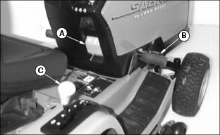
Using the Park Brake

1. Push brake pedal (A) all the way down.
2. Lift park brake lever (B) up.
3. Release pedal and park brake lever. Pedal should stay down and park brake lever should stay LOCKED in UP position.
1. Push and hold brake pedal (B) down.
2. Push park brake lever (A) down to UNLOCK park brake.
Using Headlights
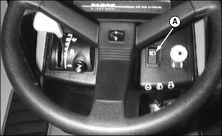
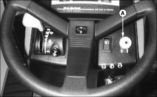
Push top of light switch (A) to turn headlights ON.
Push bottom of light switch to turn headlights OFF.
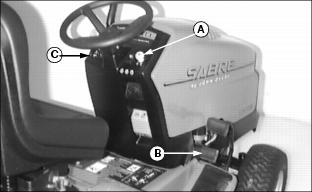
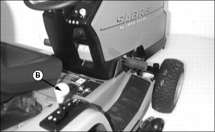
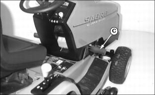
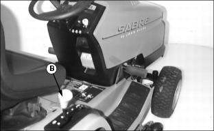
Checking Indicator Lights and Hour Meter
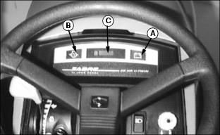
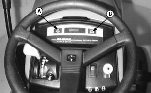
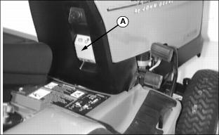
· BATTERY DISCHARGE light (A) should go out when throttle lever is moved to the HIGH IDLE/Mowing position. The voltage light may remain on for several minutes while the battery is being charged.
· OIL PRESSURE light (B) will come on when engine starts and should go out within 5 seconds.
If indicator lights stay on longer than given time, STOP engine.
· HOUR METER (C) shows the number of hours the engine has run. To display hours, key must be in the "ON" position. Check the hour meter daily to see what services need to be done. (See the Service Interval Chart in this manual and the Maintenance Schedule in your Engine Owner's Manual.)
Starting Engine
IMPORTANT: Avoid damage! Do not operate starter more than 20 seconds at a time. If engine does not start: Wait two minutes before you try again. See Troubleshooting section. |
NOTE: Engine will not start unless: PTO switch is DISENGAGED, park brake is LOCKED or brake pedal pushed down.
Picture Note: Gear model shown
2. Push PTO switch (B) down to DISENGAGE.
3. On GEAR model: Move transmission shift lever (C) to N (NEUTRAL) position.
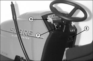
4. Pull choke knob (F) out to the ON position.
5. Move throttle lever (D) to the HALF-SPEED position.
6. Turn key (E) to START position.
7. When engine starts, release key to RUN position.
9. Let engine run for a couple of minutes to warm-up before operating tractor.
Warming and Idling Engine
· Run Engine at half speed for 2-3 minutes.
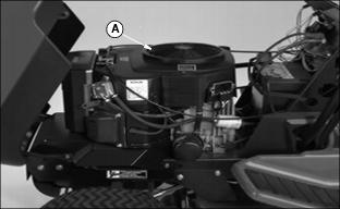
Picture Note: 2554HV Engine Shown
· Engine is air-cooled and needs a large volume of air to keep cool. Keep air intake screen (A) on top of engine clean.
· Avoid unnecessary engine idling.
Stopping Engine
1. ON MODELS 1948GV/HV, 2148HV and 2354HV: Move throttle lever (A) to SLOW position. Let engine run at low throttle a few seconds.
ON MODEL 2554HV: Move throttle lever (A) MIDWAY between slow and fast positions. Let the engine run a minimum of 15 seconds.
2. Turn key (B) to OFF position.
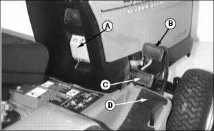
Using and Stopping Automatic Transmission
· Before moving forward or rearward, make sure area is clear of bystanders, especially children. |
To Travel Forward:

To Travel in Reverse:
NOTE: The engine and any operating attachment will stop as the REVERSE pedal is depressed with attachment engaged.
1. Bring the vehicle to a stop.
2. Push PTO knob down to the OFF position to disengage attachment.
3. Look behind the vehicle to be sure there are no bystanders nearby.
For Emergency Stopping:
1. Push down on brake pedal (C). Travel pedals (A and B) will return to NEUTRAL position.
Using and Stopping Gear Transmission
· Before moving forward or rearward, make sure area is clear of bystanders, especially children. |
To Travel Forward:
2. Push down on clutch pedal (A).
3. Move shift lever (B) to desired forward gear.
4. Release clutch pedal slowly.
To Travel in Reverse:
NOTE: The engine and any operating attachment will stop as the gear shift lever is moved to R (REVERSE) position with attachment engaged.
2. Push clutch pedal and brake (C) all the way down to STOP tractor.
3. Push PTO knob down to the OFF position to disengage attachment.
4. Look behind the vehicle to be sure there are no bystanders nearby.
5. Move shift lever (B) to R (REVERSE) position.
6. Release clutch pedal slowly.
For Emergency Stopping
1. Push down on clutch pedal and brake at the same time.
NOTE: This tractor is equipped with a Brake/Clutch Interlock. Pressing the brake pedal will also depress the clutch pedal for emergency stops.
Using Lift Lever to Raise and Lower Mower
Check out the two different lift lever positions before operation:
· TRANSPORT (UPPER) POSITION: Raises mower for transport.
· MOWING (LOWER) POSITION: Maintains cutting height set by mower height control yet allows deck to float over uneven terrain.
To put mower in MOWING (lower) position:
1. Pull lift lever (A) back slightly.
3. Push lever forward until it latches down.
To put mower in TRANSPORT (upper) position:
1. Push down on lift lever (A) slightly.
3. Pull lever back towards you until it latches.
Engaging Mower
IMPORTANT: Avoid damage! Operate mower at HIGH IDLE/Mowing when mowing or after mower blades are engaged. Machine may require 2-3 minutes warm-up period before engaging the mower deck. |
2. Move throttle lever (A) to the FAST position.
3. Lower mower to cutting height.
4. Pull PTO switch (B) up to ENGAGE mower.
NOTE: Any operating attachment and the engine will stop as the REVERSE foot pedal is depressed with attachment engaged.
5. Disengage PTO before shifting to REVERSE.
Disengaging Mower
Push PTO switch (A) down to DISENGAGE mower.
If you hit an object with mower while mowing, STOP mower and engine immediately. Inspect mower for damage.
Dismounting to Inspect or Unplug Mower or Optional Bagger
2. Push PTO switch down to DISENGAGE mower.
3. Move throttle lever to SLOW position.
8. Wait for all moving parts to STOP.
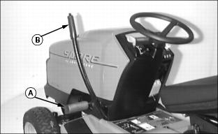
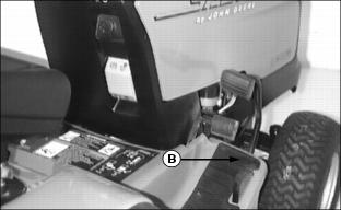
Pushing Machine
To move machine when engine is STOPPED:
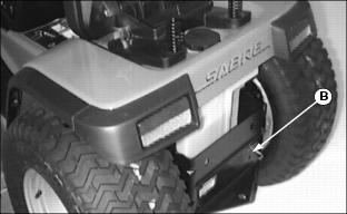
2. Pull out on free-wheeling lever (B).
3. Push machine to desired location.
NOTE: Push free-wheeling lever (B) IN before operating tractor.
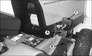
Using Reverse Implement Option
NOTE: Operating the mower while backing up is strongly discouraged. The Reverse Implement Option should be used ONLY when operating another attachment or when the operator deems it necessary to reposition the machine with the mower engaged.
1. Stop the machine FORWARD travel with the attachment still engaged.
2. Look behind the vehicle to be sure there are no bystanders.
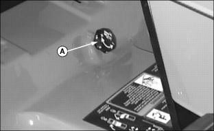
3. Lift and hold the PTO knob (A) up past the PTO engagement position to activate the reverse implement position while depressing REVERSE foot pedal slightly.
NOTE: If the engine and attachment stop while repositioning the machine, return PTO knob to the OFF position and restart the machine. (See Starting The Engine in this section.) Begin again with Step 2.
4. As the machine begins to move backward, release the PTO knob and reposition the machine.
5. Resume FORWARD travel. The attachment should continue operating.
6. Repeat Steps 1 through 5 to reposition the machine again.
Avoid Damage to Plastic and Painted Surfaces
· DO NOT wipe plastic parts unless rinsed first. (See Correct Cleaning Care in Service-Miscellaneous section.)
· Insect repellent spray may damage plastic and painted surfaces. Do not spray insect repellent near machine.
· Be careful not to spill fuel on machine. Fuel may damage surface. Wipe up spilled fuel immediately.
Using Front Weights
NOTE: Before installing wheel weights on your machine, MAKE SURE that the tire valve stems are facing the inside.
Install front wheel weights for better stability and steering control when you use equipment such as the rear-mounted grass bagger or dumpcart.
Remove front wheel weights when not required.
Using Rear Wheel Weights
IMPORTANT: Avoid damage! When adding weight to rear of tractor, use wheel weights only. 75 lbs. (34 kg) MAX. each wheel. |
Use of rear wheel weights is recommended when an attachment, such as snowthrower or blade is used.
Using Tire Chains
Tire chains are recommended for use with snowthrower and, under certain conditions; the front blade.
Preparing Tractor for Installing Chains on Tires
· Park the tractor on a level surface.
Installing the Chains
1. Remove chains from bag and lay out flat with the cross chain hook ends facing upward. Remove any twists and tangles from cross chain and rim chain.
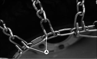
3. Drape chain over tire with the lever fastener on outside of tire and cross link hooks (A) facing upward and away from tire.
4. Adjust chain for straightness and an even amount of cross chain links on each side of tire.
5. Place the first cross chain (opposite the end with fastener and inside hook) under tire.
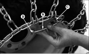
6. Pull the inside rim chain tight and hook the inside hook. Pull the outside rim chain tight and hook the outside lever fastener (B) by running the end through a free link (C). Close the fastener by rotating it back 180 degrees and engaging the hook (D) on the end of the fastener into a rim chain link (E). Make sure the chain is centered on the tire with approximately the same number of free rim links (F) on the inside and outside.
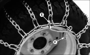
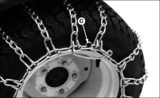
7. Tie excess rim chain links (G) back to the rim chain.
8. The chain should be as tight as possible by hand. Unhook the fastener and repeat Step 5 if the chain is loose.
9. Drive forward on chains 30'-40' and recheck for tightness. Adjust as necessary.
Transporting
Use a heavy-duty trailer to transport your machine.
Lower mower or any attachment to trailer deck.
Be sure trailer has all the necessary lights and signs required by law.
Fasten machine to trailer with heavy-duty straps, chains, or cables. Both front and rear straps must be directed down and outward from tractor.