![]()
Sabre Yard and Garden Tractors
Introduction
Product Identification
Safety
Operating
Replacement Parts
Service Interval Chart
Service Lubrication
Service Engine
Service Transmission
Service Mower
Service Electrical
Service Miscellaneous
Troubleshooting
Storing Machine
Assembly
Specifications
Warranty
Sabre by John Deere Quality Statement
Service Record
Copyright© Deere & Company

Assembly
Identify Parts
Clear Plastic Bag Contains:
Bag of Parts Contains:
NOTE: There is an extra ignition key strapped to one of the seat suspension springs.
Install Steering Wheel
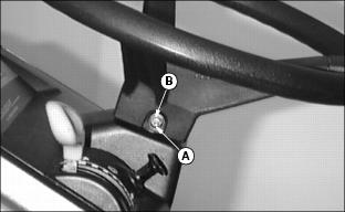
1. Put front wheels in the straight forward position.
2. Lubricate the steering shaft.
3. Install steering wheel with logo in the upright position.
4. Install shoulder bolt (A). Drive bolt in until head of bolt contacts steering wheel.
5. Install washer and nut (B).
6. Tighten lock nut until it is snug. Do not tighten lock nut to pull washer or head of bolt into steering wheel.
Add Electrolyte To Battery
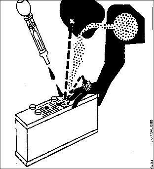
1. Use only battery-grade sulfuric acid electrolyte with 1.265 specific gravity.
NOTE: Some batteries may have shipping caps remove and discard these caps
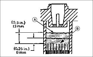
3. Slowly add electrolyte (A) until plates (B) are just covered.
4. Charge battery at 15 amps for 10 minutes or 7 amps for 30 minutes. DO NOT exceed recommended charging rate. If electrolyte starts to boil over, decrease charging rate. (See Charging Battery in the Service Electrical section.)
5. After charging, add electrolyte until level is 6 - 13 mm (0.25 - 0.5 in.) above plates.
Install and Connect Battery
1. Install battery and secure with hold-down strap (A)
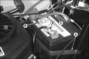
2. Remove and discard the RED positive (+) protective cap from the positive (+) battery terminal.
3. Connect blue harness wire (B) and RED positive (+) cable (C) to battery. Apply petroleum jelly or silicone spray to terminal to prevent corrosion. Make sure connection is tight. Install the red terminal cover.
4. Remove and discard the BLACK (-) protective cap from the negative battery terminal.
5. Connect black negative (-) cable (D) to battery. Apply petroleum jelly or silicone spray to terminal to prevent corrosion. Make sure connection is tight.
Check Engine Oil
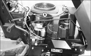
Picture Note: Model 2554HV used for photo purposes.
2. Remove dipstick (A). Wipe with clean cloth.
3. Insert the dipstick into the tube and rest the oil fill cap on the tube. Do not thread the cap onto the tube.
4. Remove dipstick to check oil level.
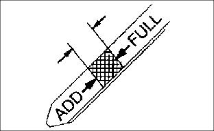
5. Oil must be between ADD and FULL marks.
6. Add oil to FULL mark if necessary. DO NOT overfill. (See Engine Oil in Service Engine section.)
7. Install and tighten dipstick. Lower hood.
Break-In Electric PTO Clutch
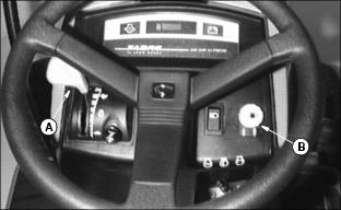
Picture Note: Model S2554 used for photo purposes.
1. Start engine and push throttle lever (A) up to full throttle (r) position.
2. With no load on mower, ENGAGE PTO (B) and allow mower to run for 10 seconds.
3. DISENGAGE PTO and wait 10 seconds.
4. Repeat Steps 2 and 3 for 12-15 cycles.
5. PTO clutch is now properly burnished.
Check Machine Safety System
Perform safety system check to make sure the electronic safety interlock circuit is functioning properly. Perform all six Tests. (See Testing Safety System in the Operating section.)