![]()
Introduction
Product Identification
Safety
Operating
Operating Foot Brake and Accelerator Pedals
Using the Directional Control Lever
Using the Charge Meter/Hour Meter
Using the Service/Drive Switch
Using the Park Brake/Emergency Stop Lever
Stopping and Parking the Vehicle
Engaging and Disengaging the Cargo Box Lock
Raising and Lowering Cargo Box
Operating the Cargo Box Tailgate
Replacing Cargo Box Tailgate Latch Rods
Carrying and Distributing a Load
Transporting the Utility Vehicle
Use Care In Handling and Servicing Batteries
Replacement Parts
Service Intervals
Service
Service Transaxle
Service Electrical
Service Miscellaneous
Troubleshooting
Storage
Assembly
Specifications
Declaration of Conformity
Declaration of Conformity
Declaration of Conformity
Service Statement
Copyright© Deere & Company

Operating
Daily Operating Checklist
Maintain desirable operational standards and help ensure the safety of the operator by routinely checking the following on a daily basis:
· Test safety systems. (roll away alarm, charger interlock and reverse warning alarm)
· Check tires for damage or cracking.
· Check operation of accelerator pedal.
· Check steering and linkages for proper operation.
· Check and make sure all vehicle safety labels are properly installed.
· Check charger and vehicle battery receptacle for damage.
· Visually inspect condition of batteries.
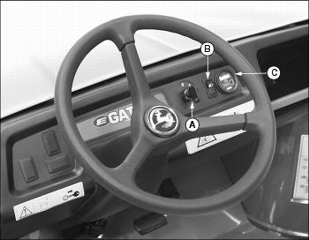
Dash Controls
Foot/Platform Controls
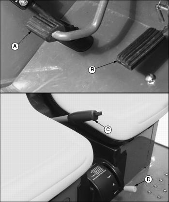
C - Park Brake/Emergency Stop Lever
Miscellaneous Controls
Picture Note: Raise operator seat to locate service/drive switch.
Operating Foot Brake and Accelerator Pedals
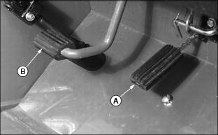
· Release accelerator pedal (A) and apply foot brake pedal (B) evenly and firmly to slow down or stop.
· Avoid hard braking applications.
· Push down the accelerator pedal slowly and smoothly when using.
· Before braking, remove foot from the accelerator pedal.
Using the Directional Control Lever
The directional control lever (A) is located on a console to the right and below the operator seat. There are three positions:
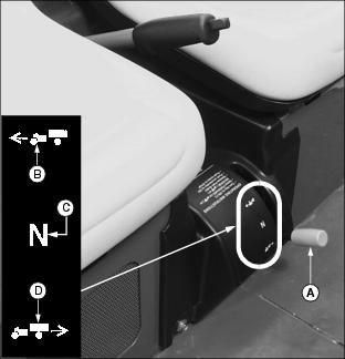
· FORWARD: Move the lever downward to position (B).
· NEUTRAL: Move lever to the middle position (C).
· REVERSE: Move the lever rearward to position (D).
Using the Charge Meter/Hour Meter
NOTE: Key switch must be turned to the ON "1" position to activate the charge meter LED display.
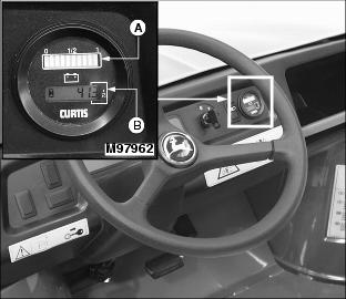
Charge Meter
When activated and during normal operation the charge meter will continuously monitor the battery charge.
The charge meter (A) has a multicolored 10-bar LED that displays vehicle state of charge. Only one LED will illuminate at a time.
· A double flashing RED 2-bar LED signals "empty" at 80% of battery discharge. This signals to the operator that the battery charge is very low and the vehicle should return to an area where the battery set can be charged.
· A flashing YELLOW 3-bar LED signals "energy reserve" at 70% of battery discharge. This signals to the operator that the battery charge is getting low.
· A GREEN 5-bar LED signals that the vehicle "energy reserve" is between 50 and 100% of battery charge.
Hour Meter
· The hour meter (B) shows number of hours the vehicle has run.
· The service interval chart gives necessary service intervals. Use the hour meter and the service interval chart to determine when the vehicle will need service.
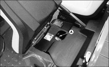
Using the Service/Drive Switch
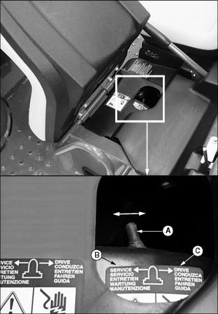
This utility vehicle is equipped with a two position service/drive toggle switch.
· Raise and tilt operator seat forward to locate switch.
Service Position
When the vehicle service/drive switch (A) is moved to the SERVICE position (B) the vehicle is disabled and prohibited from being driven.
The service/drive switch should be moved to the SERVICE position when:
· Performing any service function on the vehicle.
· The vehicle is not going to be in service for an extended period of time (one month or more).
Drive Position
When the vehicle service/drive switch (A) is moved to the DRIVE position (C) the vehicle controller is energized. When the key switch is turned to the ON "1" position, controls are energized and the vehicle is ready for normal operation.
Using the Park Brake/Emergency Stop Lever
NOTE: Applying foot brake pedal while locking and unlocking park brake/emergency stop lever decreases effort required to pull or push the park brake/emergency stop lever.
Lock Park Brake/Emergency Stop
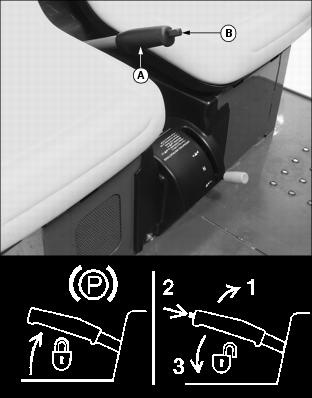
· Pull up lever (A) and latch into position.
Unlock Park Brake/Emergency Stop
NOTE: Make sure the park brake/emergency stop release button (B) is released. While the vehicle is in motion the park brake must be fully unlocked for the vehicle to operate properly.
Adjusting Seats
1. Lift and tip vehicle seat forward.
3. Slide seat forward or backward to desired position.
Starting the Vehicle
NOTE: The charger DC cable plug must be removed from the vehicle receptacle before starting the vehicle.
1. Sit on vehicle operator's seat.
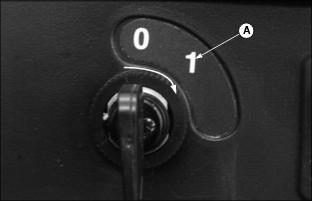
2. Turn key switch to the ON "1" position (A).
NOTE: Reverse warning indicator will sound anytime the key switch is in the ON "1" position and the directional control lever is placed in the REVERSE position.
3. Select direction of travel.

· FORWARD: Move the directional control lever (B) downward to position (C).
· REVERSE: Move the directional control lever (B) rearward to position (D).
4. Depress the foot brake pedal and unlock the park brake/emergency stop (E).
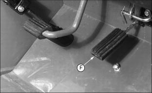
5. Slowly depress accelerator pedal (F) to start vehicle movement.
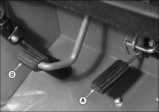
Stopping and Parking the Vehicle
1. Release the accelerator pedal (A) fully and depress the foot brake pedal (B).
2. Allow vehicle to come to a complete stop.
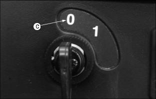
3. Turn key switch to the OFF "0" position (C).
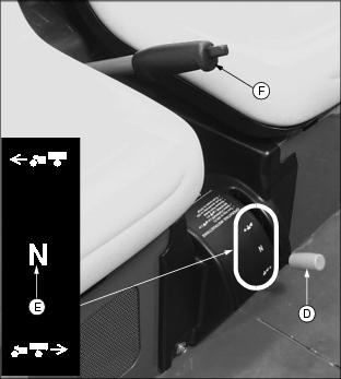
4. Move directional control lever (D) to the NEUTRAL "N" position (E).
5. Lock park brake/emergency stop (F).
Engaging and Disengaging the Cargo Box Lock
Engage Cargo Box Lock
2. Rotate lock (B) against latch (C).
Disengage Cargo Box Lock
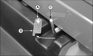
2. Rotate lock (B) completely away from latch (C).
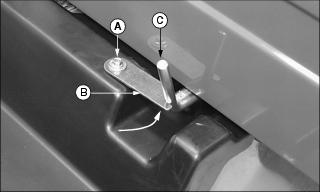
Raising and Lowering Cargo Box
Raising Cargo Box
2. Disengage cargo box lock (A).
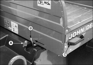
3. Push latch (B) inward to release cargo box.
4. Raise cargo box manually with lift handle (C).
Help prevent injury from an electrical shock. DO NOT touch battery terminals, connectors, or wires that are not insulated. |
NOTE: Be sure support rod is locked before leaning into battery and axle area.
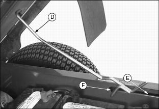
5. Support rod (D) will slide along slotted channel (E) and lock into latch slot (F).
Lowering Cargo Box
1. Raise cargo box slightly using handle (C), release support rod (D) from latch slot by pulling up on rod.
2. Slowly lower cargo box, support rod will slide along slotted channel.
· When cargo box is fully lowered, rod will latch at front of cargo box.
Operating the Cargo Box Tailgate
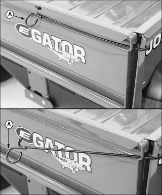
1. Push in and down on each tailgate latch rod (A).
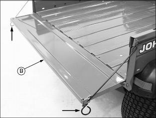
2. Pull each latch rod out and down. Lower tailgate (B) onto latch rod ends.
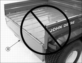
IMPORTANT: Avoid damage! DO NOT operate vehicle with the latch rods disengaged and the tailgate (B) fully lowered. Lugs on tires will catch on tailgate causing structural damage. |
Removing Cargo Box Tailgate
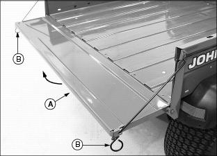
1. Raise tailgate (A) slightly. Rotate latch rod ends (B) to disengage from slots in cargo box sides.
2. Remove latch rods from each side of tailgate.
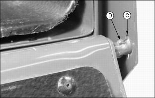
3. Swing tailgate down, align slots (C) in cargo box bracket and tabs (D) on tailgate rod.
4. Slide tailgate right or left with the tailgate rod passing through slot (C) to the outside of the cargo box bracket.
5. With one side of tailgate detached, route tailgate in the opposite direction through cargo box bracket slot to complete removal.
Replacing Cargo Box Tailgate Latch Rods
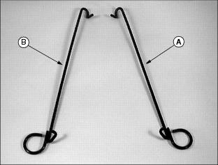
1. Identify right (A) and left (B) latch rods.
2. Route each latch rod through the bottom of tailgate slot (C).
3. Slide and rotate each latch rod within slots (C) and (D) until required position within tailgate and cargo box brackets is accomplished.
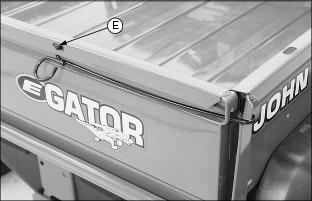
4. Raise tailgate and push in and up to engage latch rod in slot (E) in top rail.
TESTING SAFETY SYSTEMS
Use the following checkout procedure to check for normal operation of the utility vehicle.
If there is a malfunction during one of these procedures, DO NOT operate the vehicle. (See a John Deere dealer for service.)
Perform these tests in a clear open area. Keep bystanders away.
Test 1 (REVERSE WARNING ALARM)
NOTE: Perform this test with the vehicle parked on a hard, level surface.
1. Move the service/drive switch to the DRIVE position.
2. Sit on the operator's seat.
3. Lock park brake/emergency stop.
4. Turn the key switch to the ON "1" position.
5. Move the directional control lever to the REVERSE position.
· The reverse warning alarm should sound.
Test 2 (ROLL-AWAY ALARM)
NOTE: Perform this test with the vehicle parked on a hard, level surface.
1. Move the service/drive switch to the DRIVE position.
2. Sit on the operator's seat.
3. Unlock park brake/emergency stop.
4. Turn the key switch to the ON "1" position.
5. Move the directional control lever to the FORWARD position.
7. Roll vehicle forward and rearward slightly.
· The vehicle should resist movement and the roll away alarm should begin beeping.
8. Move the directional control lever to the NEUTRAL position.
9. Roll vehicle forward and rearward slightly.
· The vehicle should resist movement and the roll away alarm should begin beeping.
NOTE: The reverse warning indicator will sound.
10. Move the directional control lever to the REVERSE position.
11. Roll vehicle forward and rearward slightly.
· The vehicle should resist movement and the roll away alarm should begin beeping.
12. Turn the key switch to the OFF "0" position.
· The vehicle should resist movement and the roll away alarm should begin beeping.
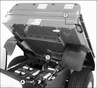
Test 3 (CHARGER INTERLOCK)
1. Move the service/drive switch to the DRIVE position.
2. Engage park brake/emergency stop.
NOTE: It is not necessary to connect the charger AC input plug to an electrical outlet when performing this test.
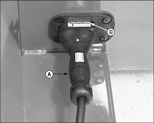
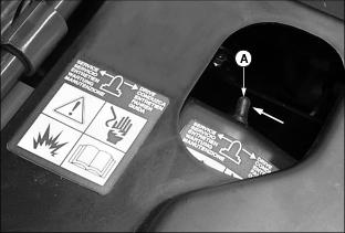
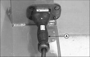
3. Connect the battery charger DC cable plug to the vehicle battery receptacle located below the operator seat on the left side of the vehicle.
· Grasp DC plug handle (A) and push plug straight into receptacle to the full engagement mark (B).
4. Turn the key switch to the ON "1" position.
5. Move the directional control lever to the REVERSE position.
· The reverse warning alarm must not sound.
6. Disconnect the DC cable plug from the vehicle receptacle.
· The reverse warning alarm must sound.
Carrying and Distributing a Load
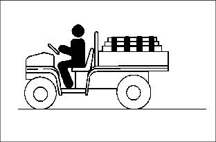
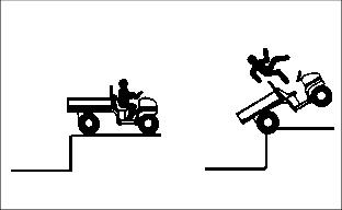
· Reduce load and ground speed when operating over rough or hilly terrain.
· DO NOT overload utility vehicle. Limit loads to those that can be safely controlled.
· On level terrain, maximum cargo box payload capacity for this utility vehicle is 227kg (500 lb.).
· When loading objects into utility vehicle, be sure load is securely anchored and evenly distributed in cargo box. Shifting loads will affect stability.
· Avoid concentrated loads at rear or side of cargo box to prevent vehicle from tipping over.
· DO NOT carry loads above height of load guard.
Avoid Overloading
Payload is more than just pounds carried, load density is more important for judging load. An example of load densities and volumes is listed using sand as a material.

NOTE: Because of the difference in weight between dry and wet sand, the only way of getting true weight of the load you are carrying is by using a weigh scale.
· For this vehicle, dry sand weighing 227 kg (500 lb.) would be approximately 1/2 of cargo box volume.
· For other materials such as those that are bagged, weight is normally printed on the bag.
· The load carrying capacity of this vehicle for example is 227 kg (500 lb.). Five bags of material weighing 45.5 kg (100 lb.) would be a full load.
Dumping a Load
· Back vehicle to area where load is desired.
· Lock park brake/emergency stop and release tailgate latches.
· When load is dumped, lower cargo box, DO NOT operate vehicle with cargo box in raised position.
Towing Loads
· Be sure to load cargo box of utility vehicle before towing a load.
· DO NOT tow a load with this vehicle that exceeds 272kg (600 lb.).
· DO NOT exceed a tongue weight of 45kg (100 lb.).
· DO NOT exceed maximum horizontal force on the hitch of 2446 N (550 lb.).
· Never exceed 16 km/h (10 mph) when towing a load. Tow load at a speed slow enough to maintain control.
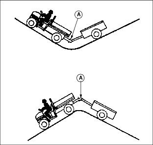
· Always use hitch point provided on, and hitches approved for the utility vehicle. They are the approved hitch point and hitches, DO NOT modify in any way.
Towing the Utility Vehicle
IMPORTANT: Avoid damage! DO NOT tow utility vehicle in excess of 15 mph (24 km/h) or motor may rupture or disintegrate. |
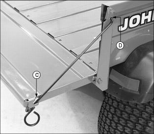
NOTE: When the service/drive switch is moved to the SERVICE position the utility vehicle can be towed with the directional control lever in any position.
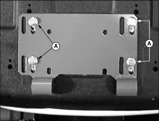
1. Move the service/drive switch to the SERVICE position (A) before towing the utility vehicle. (See Using the Service/Drive Switch in this section.)
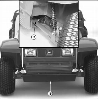
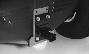
2. Attach a tow line to the utility vehicle.
· If equipped with the optional front bumper, attach the tow line securely to the front bumper mounting assembly (B).
· If vehicle is not equipped with a front bumper, attach the tow line inside the front axle (C) in the position shown.
3. Lock park brake/emergency stop.
4. Tow vehicle slowly and carefully to desired location.
Transporting the Utility Vehicle
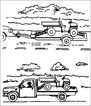
· Use a heavy-duty trailer, full size pick-up or flatbed truck to transport the utility vehicle.
NOTE: Space limitations may vary from one truck manufacturer to another. Short bed trucks do not have the necessary length requirement to accommodate the utility vehicle. Vehicle width to outside of tires is 1524 mm (60 in.).
· Turn key switch to the OFF "0" position.
· Move shift lever to the NEUTRAL "N" position.
· Lock park brake/emergency stop.
· Fasten machine to trailer with heavy-duty straps, chains, or cables. Both front and rear straps must be directed down and outward from the vehicle.
· Trailer or truck must have all signs and lights required by law.
Use Care In Handling and Servicing Batteries
Prevent Battery Explosions

Batteries contain sulfuric acid and produce explosive mixtures of hydrogen. Because hydrogen gas is present even when the utility vehicle is not in operation, make sure batteries are stored and serviced in a well ventilated area.
· Always wear proper eye, face and hand protection.
· Keep sparks, lighted matches, and open flame away from the top of battery.
· Remove all jewelry (watches, rings, bracelets, etc.) before servicing the electrical system or batteries.
· Make sure work area is well ventilated.
· Never lean over battery while testing or charging.
· Keep removable vents tight and level except when servicing electrolyte.
· Exercise caution while working with tools or conductors to prevent short circuits and sparks.
· Never check battery charge by placing a metal object across the posts. Use a battery tester, voltmeter or hydrometer.
· DO NOT charge a frozen battery; it may explode. Warm battery to 16°C (60°F).
Charging Safety
· Never attempt to charge a battery set without first reviewing the instructions provided with the charger
· Use only the battery charger provided with the utility vehicle. DO NOT use substitutes.
· Always wear proper eye, face and hand protection.
· Keep sparks, lighted matches, and open flame away from the top of battery.
· Make sure work area is well ventilated.
· Never lean over battery while testing or charging.
· Keep removable vents tight and level except when servicing electrolyte.
· To avoid dangerous sparks, make sure the charger AC plug is disconnected before disconnecting the DC plug to the vehicle receptacle.
· Never try to charge a visibly damaged or frozen battery.
· Be sure that the key switch and all electrical accessories are turned off.
· Make sure the charger leads are not broken, frayed or loose.
· If the battery becomes hot, or if violent gassing or spewing of electrolyte occurs, unplug the charger AC source first before removing the DC plug.
· If battery set is on charge, unplug the charger AC plug before disconnecting the charger DC cable plug to avoid dangerous sparks.
Using the Battery Charger
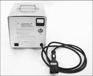
NOTE: Locally appropriate AC cord set must be supplied by the customer.
The battery charger is included with every utility vehicle. The charger is totally automatic and has no controls.
The charger monitors the battery set state of charge and contains an electronic timer that automatically turns the charger off as the batteries reach full charge.
The charger is a taper charge type which automatically decreases the rate of charge to provide good equalization of battery cells and reduce water usage.
Battery Charger Safety
IMPORTANT: Avoid damage! Help reduce the risk of injury or damage to the vehicle. Read and follow all safety warnings and operating instructions supplied with and inscribed on top of the charger. |
Charging Procedure
IMPORTANT: Avoid damage! An improper battery charging procedure may shorten battery life. DO NOT use battery additives, the life of the batteries can be shortened. |
· Become familiar with the operating instructions issued with the charger.
NOTE: Charging batteries for short intervals when the vehicle is not being used is permissible. In cold weather batteries should be taken off charge just prior to use.
· Batteries are to be charged after each period of use.
· DO NOT charge the batteries if the utility vehicle is not used that day.
· DO NOT allow batteries to set in a state of discharge.
· Prior to using the utility vehicle each day, always make sure the batteries are fully charged.
NOTE: Locally appropriate AC cord set must be supplied by the customer.
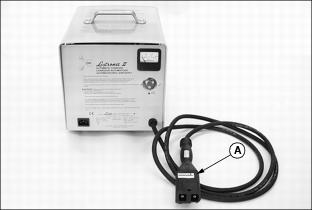
1. With the battery charger DC output cable plug (A) disconnected from the vehicle, connect the AC input plug to a properly grounded outlet.
NOTE: The vehicle battery set can be charged with the service/drive switch in the SERVICE or DRIVE position.
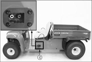
2. Connect the DC output cable plug to the battery receptacle (C) located below the operator seat on the left side of the vehicle.
NOTE: This utility vehicle is equipped with a charger interlock feature. Electrical current to the ignition is locked out when the DC outlet plug is connected to the vehicle battery receptacle.
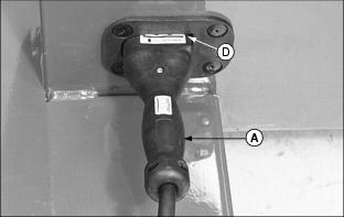
· Grasp the DC output plug handle (A) and push the plug straight into the receptacle to the full engagement mark (D).
· The charger will turn on with an audible "click" and "hum" after a short 3-10 second delay.
IMPORTANT: Avoid damage! DO NOT allow the battery charger to operate more than 30 minutes with the charge rate over 25 amperes. This is misuse and will cause overheating and transformer burnout. |
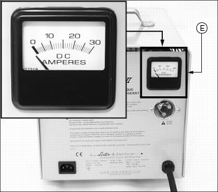
3. Monitor the ammeter (E) for the initial charge rate.
NOTE: If the batteries are heavily discharged, or the AC input line voltage is higher than nominal, the charge rate may exceed 25 amperes. Under normal conditions, the charge rate will taper to less than 25 amperes within 30 minutes.
· The initial charge rate will vary between 16 and 25 amperes depending upon the state of battery discharge and AC line voltage.
· The charge rate will decrease to 4-9 amperes for the last few hours of charge if all batteries are good.
· The charger turns off automatically when the batteries reach full charge.
· As batteries age, it is normal for the charge rate to increase above the 4 to 9 amp finish rate. The charger will still determine when the batteries are as charged as they can be and then turn off.
· The required charge time varies with the depth of the discharge. Under normal conditions, the typical charge time is 10-12 hours. This is the normal charge time for batteries which have been discharged to 80% of their capacity.
As much as four additional hours may be required to properly charge the batteries under the following conditions:
· Heavily discharged batteries (more than 80% discharged).
NOTE: When charging new or cold batteries, a higher than normal finishing charge voltage can be expected. This results in a low finish charge rate (2-5 amperes), and additional time is required to achieve equalization of all battery cells.
· Charging new batteries (batteries with less than 20 to 50 discharge/charge cycles).
· Charging optional larger batteries.
4. Disconnect the DC output cable plug from the vehicle receptacle.
· Grasp the DC output plug handle (A) and pull the plug straight out of the receptacle.