![]()
Introduction
Safety Signs
Controls
Installing Mower
Operating the Mower
Replacement Parts
Optional Equipment
Service Machine Safely
Service Intervals
Service Mower
Avoid Injury From Contacting Blades
PERFORM LUBRICATION AND MAINTENANCE
Hydraulic Routing-Rear Center Cutting Unit
Hydraulic Routing-Rear Right-hand Cutting Unit
Hydraulic Routing-Rear Left Hand Cutting Unit
Hydraulic Routing-Right Center Cutting Unit
Hydraulic Routing-Front Right-Hand Cutting Unit
Hydraulic Routing-Front Left-Hand Side
Hydraulic Routing-Left Center Cutting Unit (Optional 7-Gang)
Hydraulic Routing-Valve Block (Optional 7-Gang Electro-Hydraulic(EH)
Hydraulic Routing-Flow Divider (Optional 7-Gang Electro-Hydraulic (EH)
Hydraulic Routing-Electro Hydraulic Valve
Hydraulic Routing-Tee Union (Optional 7-Gang)
Service Miscellaneous
Service Technical
Troubleshooting
Storage
Assembly
Specifications
John Deere Quality Statement

Service Mower
Avoid Injury From Contacting Blades
KEEP SERVICE AREA CLEAN
Understand service procedure before doing work.
Keep all parts in good condition and properly installed. Fix damage immediately. Replace worn or broken parts. Remove any buildup of grease, oil, or debris.
Grease
Use grease based on the expected air temperature range during the service interval.
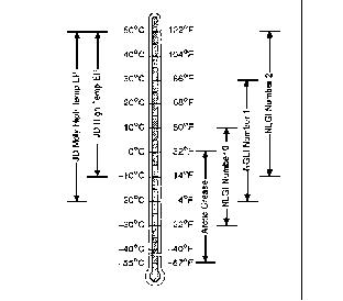
NOTE: Lubricate IMMEDIATELY after washing the machine to remove water before bearings cool and "suck in" water and contaminates.
The following greases are preferred:
· John Deere MOLY HIGH TEMPERATURE EP GREASE
· John Deere HIGH TEMPERATURE EP GREASE
Other greases may be used if they meet one of the following:
· SAE Multipurpose EP Grease with a maximum of 5% molybdenum disulfide.
Greases meeting Military Specification MIL-G-10924F may be used as arctic grease.
PERFORM LUBRICATION AND MAINTENANCE
IMPORTANT: Avoid damage! The recommended intervals are based on normal conditions. Severe or unusual conditions may require shorter intervals. |
NOTE: Do not overfill as oil may expand during operation and spill on turf.
Clean grease fittings before lubricating. Replace lost or broken fittings immediately.
MOWER HYDRAULIC OIL
Use John Deere J20C specifications or an equivalent. DO NOT use type "F" automatic transmission fluid or J20D Low viscosity HY-GARD. John Deere HY-GARD (J20C) transmission oil is specially formulated to provide maximum protection against mechanical wear, corrosion, and foaming.
CUTTING UNIT GEAR CASE GREASE
John Deere Cotton Picker Spindle Grease is recommended for cutting unit gear case.
If other grease is used, us e SAE Multipurpose Grease meeting NLGI Consistency Number 00.
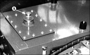
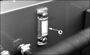
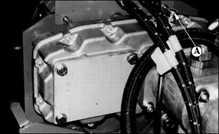
CUTTING UNIT GEAR CASE
Pack gear case to fill plug (A) with John Deere Cotton Picker Spindle Grease or other SAE Multipurpose Grease meeting NLGI Consistency Number 00. See Cutting Unit Gear Case Grease in this section.
Gear case capacity is 0.4 L (0.8 pt).
BEFORE EACH USE
1. Check hydraulic oil level in tank. Add oil as necessary.
3. Inspect hoses for wear. Replace damaged hoses.
4. Check for oil leaks. Tighten fittings and replace seals as necessary.
5. Check for bent or broken reels and replace.
IMPORTANT: Avoid damage! Damaged reels will provide an uneven cut and could cause damage to the machine's hydraulic system. |
6. Check cutting reel and bed knives for sharpness and nicks.
7. Check reel-to-bed knife settings and adjust as necessary.
Hood
Keep the rear part of the hood (A) in an upright position using the hood support as shown.
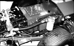
Changing Hydraulic Oil
NOTE: The hydraulic oil must be changed every 500 hours or annually whichever comes first.
1. Unscrew the filler cap (A) and drain plugs in bottom of tank (not shown), before draining oil.
2. Refill with clean hydraulic oil (Approx 24 gal. (90 L).
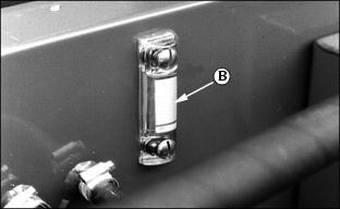
3. Check sight gauge (B) and replace filler cap.
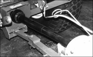
Gear Case Oil Change
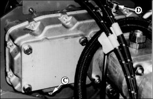
Change oil after the first 50 hours of operation. After that check oil level every 100 hours of operation. Change oil every 500 hours or annually which ever comes first.
Unscrew drain plug (C) and filler plug (D) for draining oil. Replace drain plug and refill with 20 oz. (.6 L) of SAE-90 weight gear lube.
Recheck level with dipstick on top filler plug
Daily
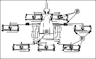
IMPORTANT: Avoid damage! After operating wash machine and grease rollers to flush contaminants from bearings. |
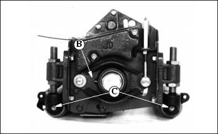
Grease reel bearing (B) on each cutting unit.
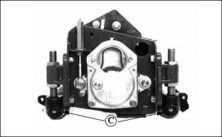
Grease rollers (C) on front and rear of cutting units after washing.
Every 8 hours
Check reservoir oil level by checking sight gauge (A). If oil level is not at the black line, wipe surrounding area before removing cap. Fill with J20C or equivalent, Reservoir capacity is 24 gal. (90 L).
· Inspect hoses for nicks, cuts, or kinks.
· Look for signs of oil leaks. Tighten fittings or replace seals.
· Check cutting reels and bed knives for sharpness and nicks
· Check PTO driveline and grease.
Every 25 hours
· Fill with John Deere SAE 90 Gear oil.
· Check tightness. Torque to 35 lb-ft. (47 N·m).
After First 50 Hours of Use.
Replace oil filter. (See Replacing Oil Filter, this section.)
Every 500 Hours
Pack gear case with John Deere Cotton Picker Spindle Grease or other SAE Multipurpose Grease meeting NLGI Consistency Number 00.
Gear case capacity is 0.8 pt (0.4 L).
Yearly or Every 500 Hours
NOTE: Replace oil filter element after the first 50 hours of operation.
1. Replace oil filter element. (See Replacing Oil Filter in this section).
2. Remove suction element and clean in solvent. (See removing suction element in this section.)
3. Drain, flush, and fill system with new hydraulic fluid to help prevent condensation buildup and damage to the system.
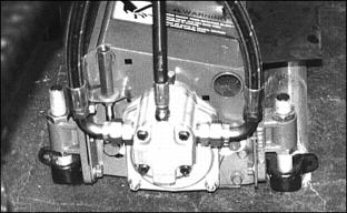
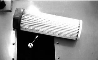
Removing Suction Element
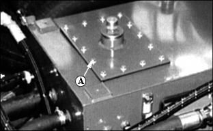
2. Remove 14 screws, plate (A) and rubber gasket under plate.
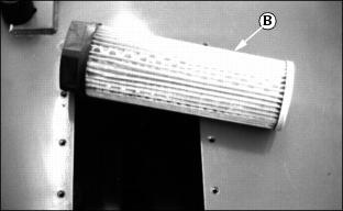
3. Remove suction element (B). Clean element with solvent or replace element.
5. Drain, flush and refill system with new hydraulic fluid. (See Hydraulic Drive System in this section for type of oil to use.)
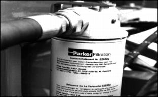
Replacing Oil Filter
NOTE: The hydraulic system has two filters: a suction filter (A) and a return filter (B).
The suction filter (A) must be cleaned every 500 hours of operation.
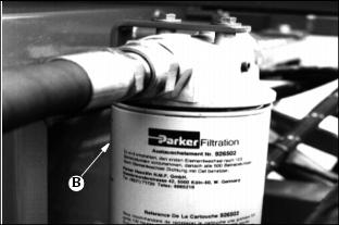
The return filter (B) must be replaced after the first 50 hours of operation and every 500 hours thereafter.
Replacing Return Filter
1. Clean debris and dirt from filter area.
3. Put oil on new filter gasket. Install filter.
Lubricate Weekly
Use this chart to locate the lubrication points.
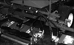
Hydraulic Routings
The following illustrations show the routing of hydraulics (the 7-gang configuration is shown).
IMPORTANT: Avoid damage! Hydraulic leaks and hose failure may cause damage to machine and turf area. Install hoses properly. |
Keep hoses free of twist and kinks before and after tightening fittings.
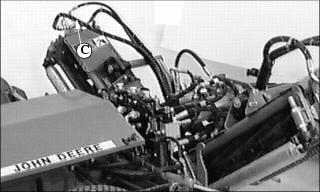
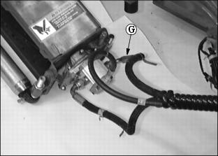
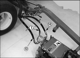
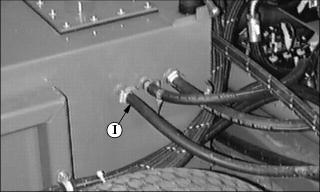
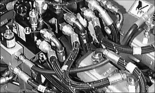
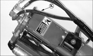
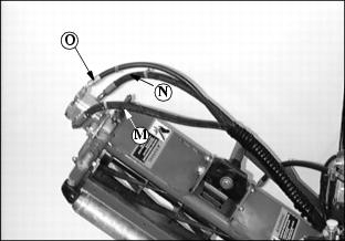
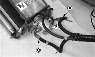
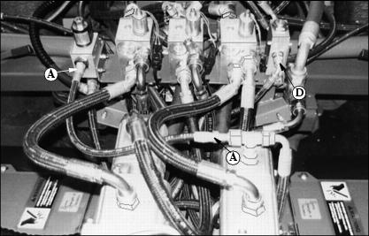
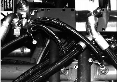
Hydraulic Routing-Rear Center Cutting Unit
Letters are shown where one routing begins and ends.
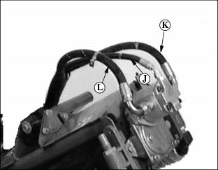
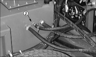
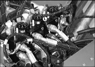
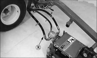
Hydraulic Routing-Rear Right-hand Cutting Unit
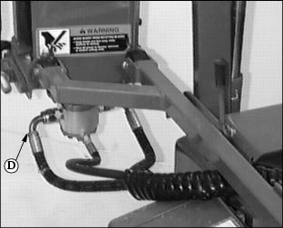
Picture Note: Left rear cutting unit.
Picture Note: Right rear cutting unit.
Picture Note: Rear reservoir ports (Motor drain return lines)
Picture Note: Top port of center valve (Backlap valves shown)
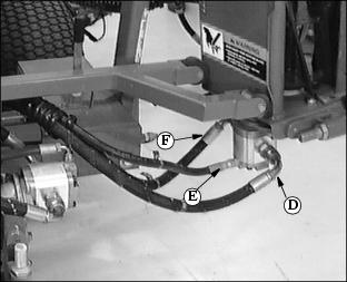
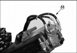
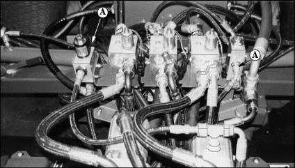
Hydraulic Routing-Rear Left Hand Cutting Unit

Picture Note: Rear left cutting unit
Picture Note: Rear right cutting unit
Picture Note: Rear port on reservoir (Motor drain lines)
Picture Note: Bottom port center valve (Backlap valve shown)
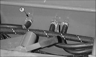
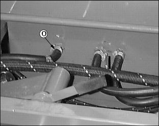
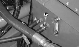
Hydraulic Routing-Right Center Cutting Unit
Picture Note: Left center cutting unit
Picture Note: Right center cutting unit
Picture Note: Right side of reservoir (Motor drain lines)
Picture Note: Top port of left valve (Backlap valves shown)
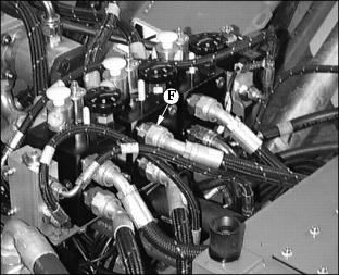
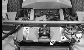
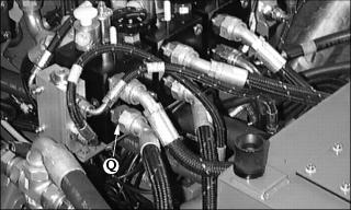
Hydraulic Routing-Front Right-Hand Cutting Unit
Picture Note: Front left cutting unit
Picture Note: Front right cutting unit
Picture Note: Right side of reservoir (Motor drain lines)
Picture Note: Bottom port of right valve
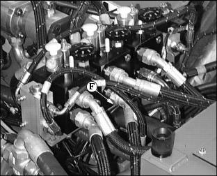
Hydraulic Routing-Front Left-Hand Side
Picture Note: Front left cutting unit
Picture Note: Front right cutting unit
Picture Note: Back of reservoir (Motor drain lines)
Picture Note: Rear center cutting unit
Hydraulic Routing-Left Center Cutting Unit (Optional 7-Gang)
Picture Note: Left side center cutting units
Picture Note: Right side center cutting unit
Picture Note: Left side reservoir
Picture Note: Left valve bottom port (Optional backlap valve shown)
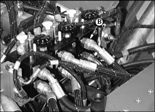
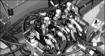
Hydraulic Routing-Valve Block (Optional 7-Gang Electro-Hydraulic(EH)
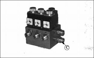
Picture Note: Electro hydraulic valve-lower port
Picture Note: Over center lift valve
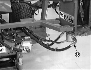
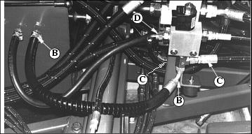
Hydraulic Routing-Flow Divider (Optional 7-Gang Electro-Hydraulic (EH)
Picture Note: Flow divider on left side top port to rear port on valve block
Flow divider-top port to right center lift cylinder
Flow divider-lower port to left center lift cylinder
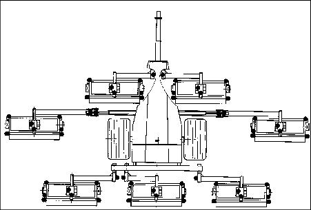
Hydraulic Routing-Electro Hydraulic Valve
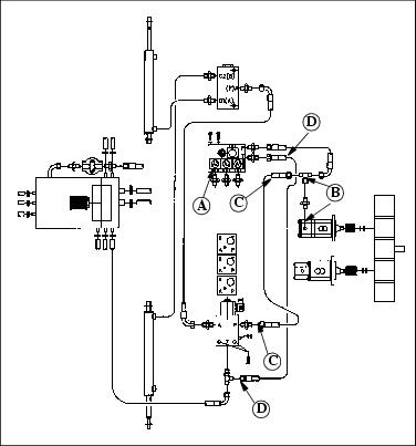
The 7-gang electro-hydraulic configuration is represented by the line art above. Key (A) is the Electro-Hydraulic valve. Follow the routing with the corresponding letters.

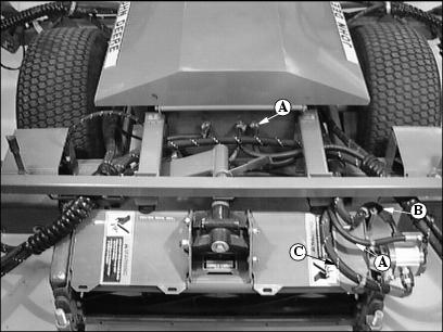
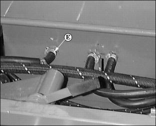
Hydraulic Routing-Tee Union (Optional 7-Gang)
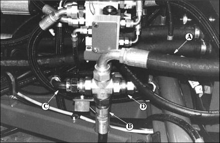
Return hose (A) goes from collection TEE to return filter. B, C, and D are return lines from solenoid valves.
Solenoid valve return lines to TEE (A). (Backlap valve shown)