![]()
Introduction
Safety Signs
Controls
Installing Mower
Operating the Mower
Replacement Parts
Optional Equipment
Service Machine Safely
Service Intervals
Service Mower
Service Miscellaneous
Service Technical
Troubleshooting
Storage
Assembly
5-Gang Standard Mower Installation
Install Front Roller (Optional)
Install Scraper Blade (optional)
Install Grass Deflector (Optional)
Install Cross Cutting Kit (Optional)
Mowing without Cross Cutting Kit
Mowing With Cross Cutting (Front)
Installation Cross cutting 7-Gang Lift Arms
Mowing with Cross Cutting (7-Gang)
Mowing Without Cross Cutting Kit (7-Gang)
Specifications
John Deere Quality Statement

Assembly
Unpack Shipping Crate
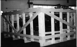
1. Remove top, sides, and cross supports of crate. Cut and remove tie bands on tires and motors.
2. Remove two boxes and remove items.
3. Attach chain hoist to axle and safely remove from pallet.
4. Set unit on a level surface, block front of unit in a level frame position.
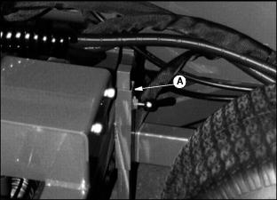
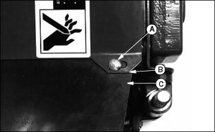
5. Set rear frame support (A) in the down position.
NOTE: Unit shipped without oil in reservoir
5-Gang Standard Mower Installation
Installation 5-Gang Mower
1. Install a pin (A) in each lift arm, rear and center with a hex head screw and spring washers (B).
2. Mount roller support (C) onto the frame with M10x65 Screw, flatwasher and nuts as shown.
3. Mount the pivots (D) onto the cutting units, with hardware supplied with cutting units.
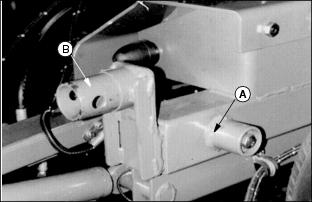
4. Remove reel pivot (A) from machine and install on reel cutting unit.
5. Pivot can be installed in fixed position (B) or float position (C).
NOTE: When installing in float position (C), slowly tighten lock nut (D) only to the point where there is still "full free float" in slot.
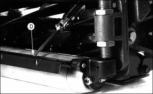
6. Mount the cutting units onto the lift arms (D) with a patchback hex head screw and washer.
NOTE: If front rollers and adjusters are not used on the cutting unit, install stop bracket on inside adjuster mounting face.
Disregard if front roller and adjusters are not used on cutting units
If front rollers and adjusters are not used cutting units can be operated in fixed head position only.
7. Align tractor drawbar to mower hitch on a level surface.
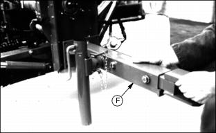
8. Select height position for mower hitch (F) which ensures that the mower frame is horizontal when hitched to the tractor drawbar.
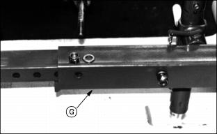
9. The hitch must be set at a proper length for specific tractor. Select holes on mower hitch (G) and secure hitch with M16x110 hex head screws, washers and lock nuts.
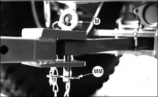
10. Attach the mower to the tractor with hitch pin (M). Secure with lock pin (MM).
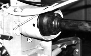
11. Install hose guide (K) with two M8x30 bolts, flatwashers and locknuts.
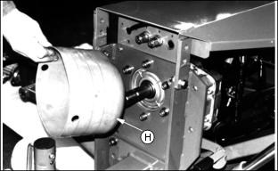
12. Install the P.T.O. shield (H) with two fillister head screws M10x30 and washers.
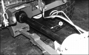
13. Connect the P.T.O. driveline (I) to both tractor and mower. Pull back on quick coupler and slide PTO shaft onto stub shaft of the tractor.
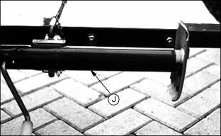
14. Rotate and secure jackstand in storage position (J).
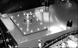
15. Unscrew filler cap (L) and fill tank with 90 L (24 gal) of hydraulic oil. Check with oil level indicator.
NOTE: John Deere HY-GARD Transmission oil (J20C) should be used.
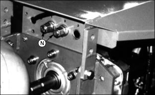
16. Remove the plug fittings (N) and install hydraulic lines (customer supplied) from tractor to mower from SCV ports with float or "detent" position.
Electrical Plug Sockets
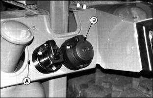
1. Install plug socket on a suitable place at the backside of the tractor (A).
2. Connect the brown wire with the ground (-) wire of the tractor. Connect the red (+) wire with the ignition lock via a fuse.
Connect the plug from mower cable (B) with plug socket.
NOTE: (B) optional socket for electro-hydraulic lift kit
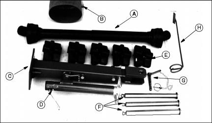
Install Front Roller (Optional)
1. Remove cap plugs from ends of roller shaft.
2. Insert grease fittings (A) in both ends.
3. Thread nut (B) approximately 1 in. from bottom of threaded adjuster shaft.
4. Thread set screw (C) half way into adjuster with hex hole for allen wrench facing out.
5. Thread jam nut (D) onto set screw.
6. On adjuster for other end, just thread nut onto adjuster shaft approximately 1 in. from bottom of adjuster. There is no hole for set screw in this adjuster.
NOTE: Tip reel on its back roller side for easier front roller assembly. Adjuster mounting brackets are offset. If grass is to be cut 1-1/2 in. or less, "long" end (A) of bracket goes toward the bed knife. This is the way the rear rollers are installed from the factory. If grass is to be cut 1-1/2 in. or higher, "short" end (B) of bracket goes toward the bed knife.
7. Align pin (C) in adjuster mounting bracket with hole in attaching bracket.
8. Attach adjuster mounting bracket with cap screws.
NOTE: FINGER TIGHTEN cap screws. Bracket must be allowed to move until roller is assembled.
IMPORTANT: Avoid damage! One end of roller shaft has flats on it. The height adjuster with the set screw also has flats in the roller shaft mounting hole. The two must be on the gear box end of reel. |
9. Attach height adjusters to roller shaft. Flats on roller shaft and adjuster MUST be on gear case end of reel.
10. Insert threaded shafts through adjuster mounting brackets.
11. Thread nuts (D) onto shafts FINGER TIGHT only.
12. Center roller between right and left height adjusters. Gap (A) should be the same on both ends. Tighten set screw (B) and jam nut (C).
IMPORTANT: Avoid damage! Tightening sequence MUST be followed. This will self-align the rollers to the adjusters and brackets. |
13. Tighten top nuts (D) on left and right-hand adjusters with 36 mm wrench provided with machine.
14. Tighten adjuster mounting bracket nuts (E) on left and right sides of reel.
Install Scraper Blade (optional)
NOTE: There is a right and left hand spring. Each spring has a long and short leg.
1. Insert short leg (A) of springs through slots in both ends of scraper.
2. Slide rod (B) through scraper and springs.
3. Place long leg of spring in groove (A) of height adjuster. Press down and push rod into hole (B) of height adjuster.
4. Follow same procedure for other end of scraper.
5. Align hole in rod with slot in center of scraper and drive roll pin (C) in flush with top of scraper.
NOTE: To clean scraper, place screw driver in either slot (D) in scraper and push towards reels. Scraper will lift for easier cleaning under it.
Install Grass Deflector (Optional)
1. Install grass deflector UNDER slotted bracket.
2. Install carriage bolts (A) through slots, then deflector.
3. Assemble flat washer (B) and lock nut (C) under deflector.
4. Tighten nuts until washers are only up to deflector. Deflector MUST be able to move after tightening to allow for expansion and contraction due to temperature changes.
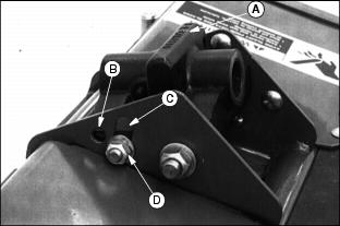
Install Reel Motor
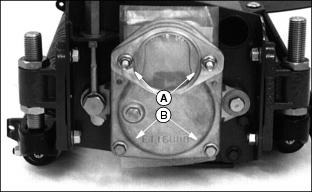
1. Remove 4 nuts (A), 2 bottom bolts (B), and gear cover.
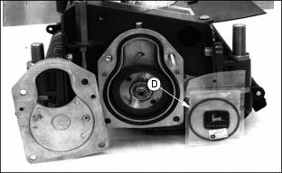
2. Remove motor O-ring (D) from inside gear case.
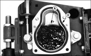
3. Fill gear case to top of reel drive gear (A) with John Deere Cotton Picker Spindle Grease or other SAE Multipurpose Grease meeting NLGI Consistency Number 00. See Cutting Unit Gear Case Grease in this section.
4. Be sure gear case O-ring (B) is in place.
5. Install gear case cover and fasten with 2 bottom bolts and nuts ONLY.
6. Free motor from lift arm on machine and remove protective cap from motor gear.
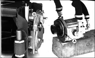
8. Install O-ring (A) (removed in step 2) to motor and assemble motor to gear box with top 2 gear box bolts (B) and nuts.
9. Grease fittings (C). See Extreme Pressure or Multipurpose Grease in Lubrication and Maintenance section.
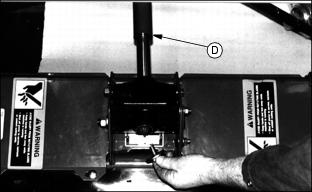
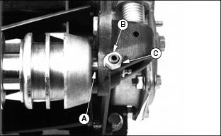
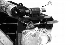
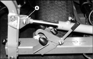
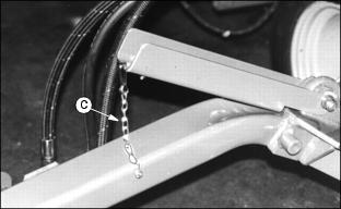
Install Cross Cutting Kit (Optional)
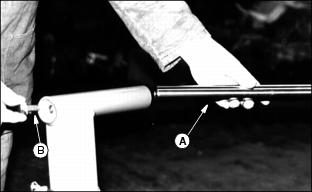
Remove lock nut and washer where reel lift cylinder is attached to the frame.
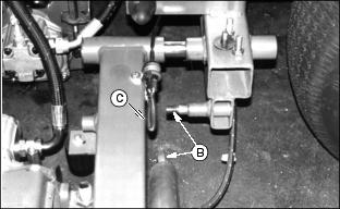
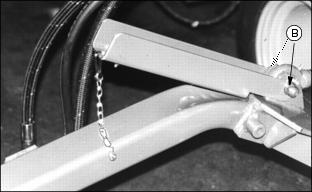
Pull the lift arm/lift cylinder assembly backwards until the cylinder is loosened from the frame (B)
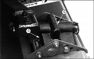
Fit the wire cable (C) on the pin (See (B).
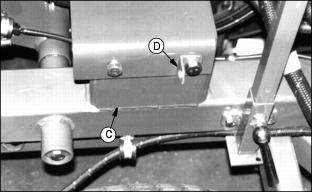
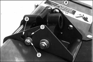
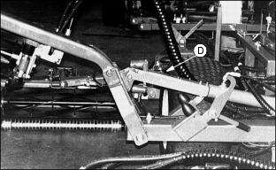
Reinstall the bracket and mount the angle iron onto the bracket as shown (D).
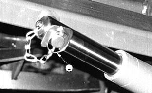
Attach the chain onto the lift cylinder (E) with a hex head screw M6 x 12 and washer.
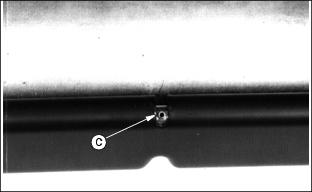
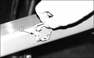
Mowing without Cross Cutting Kit
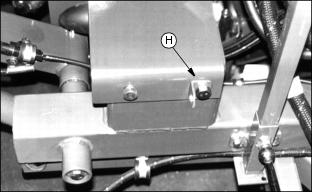
Clip the wire cable onto the angle iron (H).
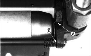
Mowing with Cross Cutting Kit
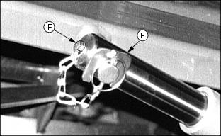
Unclip wire cable from angle iron (H), release locking plate from lift arm pin (F), place wire cable on lift arm pin and secure with locking plate.
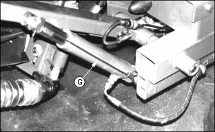
The wire cable will now limit the lifting height of the cutting units when they are being raised (G).
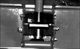
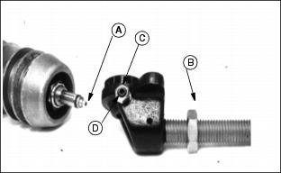
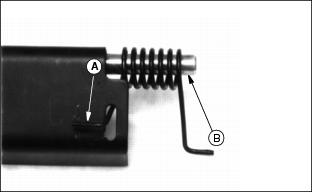
Cross Cutting Front Lift Arms
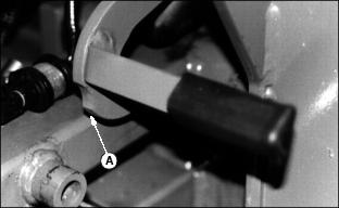
Latches left hand and right hand front have a recess (A)
Mowing With Cross Cutting (Front)
The lifting height will now be limited by the latches (B).
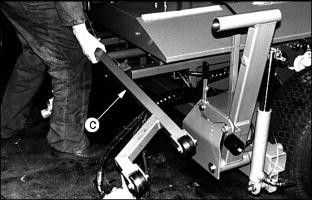
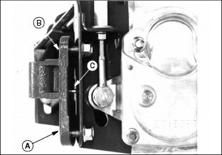
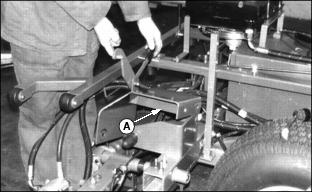
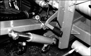
Installation Cross cutting 7-Gang Lift Arms
Release the right hand lift cylinder from the right hand lift arm (A).
Install the stop piece together with the lift cylinder, using a hex head screw M12x65, two washers and a lock nut (B).
Fit the chain onto the right hand lift arm (C).
Mowing with Cross Cutting (7-Gang)
Push stop piece onto lift cylinder (D).
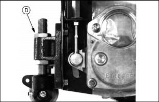
Mowing Without Cross Cutting Kit (7-Gang)
Pull off the stop piece from lift cylinder and secure with chain (C).
Adapter Piece For Jackstand
Remove cap from frame and place the adapter piece into the frame (A).
Release jackstand from mower hitch and attach it to the adapter piece (B).
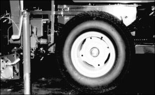
Jack up the mower and take off the wheel.
Replace the repaired wheel and continue in reverse order.