![]()
Introduction
Safety Signs
Controls
Installing Mower
Install Hydraulic Lines (5 or 7-Gang)
Operating the Mower
Replacement Parts
Optional Equipment
Service Machine Safely
Service Intervals
Service Mower
Service Miscellaneous
Service Technical
Troubleshooting
Storage
Assembly
Specifications
John Deere Quality Statement

Installing Mower
Park Tractor Safely
· Stop vehicle on a level surface, not on a slope.
· Before you leave the operator's seat, wait for engine and all moving parts STOP.
· Lower cutting units or latch in UP position when not operating.
Avoid High Pressure Fluids

· Escaping fluid under pressure can penetrate the skin causing serious injury. Avoid the hazard by relieving pressure before disconnecting hydraulic or other lines. Tighten all connections before applying pressure.
· Search for leaks with a piece of cardboard. Protect hands and body from high pressure fluids.
· If an accident occurs, see a doctor immediately. Any fluid injected into the skin must be surgically removed within a few hours or gangrene may result. Doctors unfamiliar with this type of injury should reference a knowledgeable medical source. Such information is available from Deere & Company Medical Department in Moline, Illinois, U.S.A.
Tractor Specifications
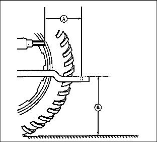
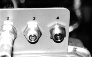
The mower can be attached to any tractor having a drawbar and 25 PTO horsepower for 5-gang and 35 hp for 7-gang minimum that conforms to ASAE-SAE standards of 356 mm (14 in.) (A) from PTO shaft to center hole in drawbar. The tractor must have a PTO speed of 540 rpm.
Drawbar height (B) should be set to conform to ASAE-SAE standards of 330 to 508 mm (13 to 20 in.).
The tractor should be equipped with turf pattern tires to minimize damage to fine turf areas. Tire pressure should be checked regularly, as this will have a considerable effect on steering traction and associated turf damage.
At least one SCV will be required to operate lift system; two are recommended. (Must have a float detent position.)
Install Hydraulic Lines (5 or 7-Gang)
NOTE: Hydraulic lines must be connected to an outlet having float capability. (See tractor operator's manual for proper operation of the float position.) If float position is not available, cutting units cannot follow ground contour.
Because of the variety of SCV positions on various tractors the user must supply hoses from the manifold position on the 365-gang mower to tractor SCV's.
Ideally use a tractor with 2 SCV' s with float position
1. Route hydraulic lines in the safest manner, making sure there are no sharp edges on the brackets that could damage hydraulic lines.
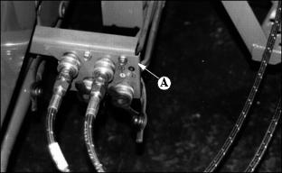
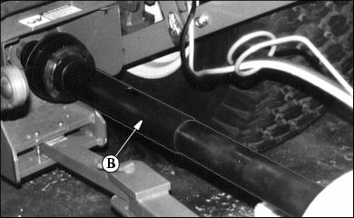
2. Connect user provided hydraulic lines from tractor outlet (A) to the feed through fitting bracket (B) on the gang mower.
NOTE: If your tractor has 2-SCV's then connect two hoses to the feed through bracket (B).
If setting up to lift cutting units together as a 5-gang replace manifold fittings with Tees (customer supplied).
If your tractor is set up with only 1-SCV with "float" then run your hoses from the lift cylinder ports to a customer installed "TEE" at the feed through bracket (B). Then run your Hydraulic hoses to the tractor SCV.
If operating as 7-gang lifting together, replace manifold fittings with a cross fitting for single lift and float.
3. Start tractor and operate controls. Check for hydraulic leaks before operating mower.
Electrical
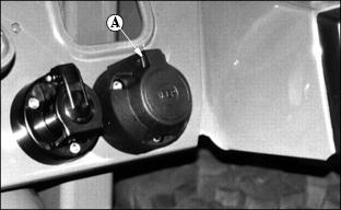
Install plug socket on a suitable place at the backside of the tractor (A).
Connect the brown wire with the ground (-) wire of the tractor. Connect the red (+) wire with the ignition lock via a fuse (See tractor manual for connecting to tractor electrical circuit.)
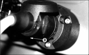
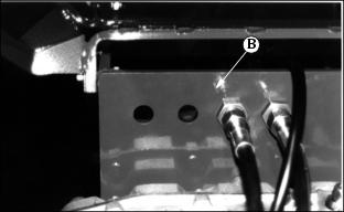
Connect plug from mower cable (B) with plug socket.
Detaching Mower
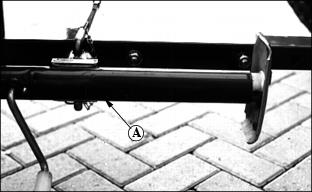
1. Remove jackstand (A) from storage location. Fasten jackstand in vertical position.
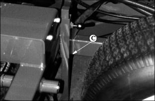
2. Lower rear support (C), located on frame right -hand rear of machine to ground and lock in place
3. Remove hydraulic lines from tractor. Put dust covers on ends of hydraulic lines to avoid contamination of hydraulic system