![]()
Introduction
Safety Signs
Controls
Installing Mower
Operating the Mower
Avoid Injury From Contacting Blades
Stay Clear of Rotating Drivelines
HELP PREVENT SERIOUS OR FATAL ACCIDENTS
ADJUSTING REEL-TO-BED KNIFE CLEARANCE
READJUST REEL-TO-BED KNIFE CLEARANCE
Replacement Parts
Optional Equipment
Service Machine Safely
Service Intervals
Service Mower
Service Miscellaneous
Service Technical
Troubleshooting
Storage
Assembly
Specifications
John Deere Quality Statement

Operating the Mower
Operator Training Required
· Study operation section of this manual before operating the machine.
· Operate machine in an open, unobstructed area under the direction of an experienced operator.
· Learn the use of all controls.
· Operator experience is required to learn the moving, stopping, turning and other operating characteristics of the machine.
Check Ground Conditions
· Clear mowing area of objects that might be thrown. Keep people out of mowing area. Stop machine if anyone enters the area.
· Study mowing area. Set up safe mowing pattern. Do not mow under conditions where traction or stability is doubtful.
· First, test drive area with PTO OFF and cutting units lowered. Slow down when you travel over rough ground.
· If you hit an object, stop the machine and inspect it. Make repairs before you operate. Keep machine and attachments properly maintained and in good working order. Keep all shields and guards in place.
· DO NOT leave machine unattended when it is running.
· Only operate during daylight or with good artificial light.
· Be careful of traffic when operating near or crossing roadways.
Avoid Injury From Contacting Blades
Before you dismount to unplug or adjust mower:
· DISENGAGE PTO to stop reels.
· Keep hands, feet and clothing away from cutting units when engine is running.
· DISENGAGE PTO to stop reels when you are not using mower.
· Lower cutting units or latch in UP position when not operating.
Keep Riders Off
· Only allow the operator to pull the machine. Keep riders off.
· Riders on the machine or attachment may be struck by foreign objects or thrown off the machine causing serious injury.
Wear Appropriate Clothing
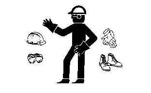
· Wear close fitting clothing and safety equipment appropriate for the job.
· Loud noise can cause impairment or loss of hearing, wear a suitable protective device such as earplugs.
· Do not wear radio or music headphones while operating the machine. Safe operation requires your full attention.
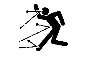
Stay Clear of Rotating Drivelines
Entanglement in rotating driveline can cause serious injury or death:
· Wear close fitting clothing.
· STOP the engine and be sure PTO driveline is stopped before getting near it.
Park Safely
· Stop machine on a level surface, not on a slope.
· Lower attachments to the ground.
· Engage park brake on tractor.
· Before you leave the operator's seat, wait for engine and all moving parts STOP.
HELP PREVENT SERIOUS OR FATAL ACCIDENTS
· Be alert at all times, drive forward carefully. People can move quickly into the mowing area before you know it.
· Back carefully. Shut off PTO and look behind the machine carefully before you back up.
· Shut off PTO when you are not mowing.
· Use extra care when you come to blind corners, shrubs, trees, or other objects that may block your vision.
· DO NOT let an untrained person operate the machine.
· DO NOT carry or let people ride on machine or any attachment.
Avoid Tipping
· DO NOT drive where machine could slip or tip.
· Stay alert for holes and other hidden hazards in the terrain.
· Slow down before you make a sharp turn or operate on a slope.
· Drive up and down a hill - not across. Be careful when you change direction on a slope.
· DO NOT stop when going up hill or down hill. If machine stops going up hill, STOP PTO and back down slowly.
Check Wheel Bolts
· A serious accident could occur causing serious injury if wheel bolts are not tight.
· Check wheel bolt tightness often during the first 100 hours of operation.
Starting Tractor Engine
3. Lower cutting units to the ground using tractor selector control valves controls. (See tractor operators manual for operation.)
5. Move throttle lever to operate tractor at 540 rpm PTO speed.
CUTTING UNITS
IMPORTANT: Avoid damage! All cutting unit adjustments and backlapping to be performed by trained personnel. |
NOTE: Refer to Safety section of this manual. Follow recommended precautions and safety practices shown.
Always wear safety glasses when making adjustments or performing maintenance on machines.
NOTE: Adjustments may affect each other. It is important that adjustments be made in the following sequence.
1. Adjust two-bolt gauge bar for desired height-of-cut.
2. Set units for the height-of-cut desired.
3. Adjust the reel-to-bed knife clearance.
4. Perform the backlapping operation.
5. Readjust reel-to-bed knife clearance.
IMPORTANT: Avoid damage! Reel must NOT contact bed knife during normal operation or overheating and damage to both reel and bed knife may occur. |
ADJUSTING HEIGHT-OF-CUT
NOTE: All cutting units must be set at the same height to obtain an even cut. Floating units will not provide a quality cut in grass over approximately 38 mm (1-1/2 in.) tall.
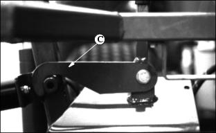
1. Raise cutting unit lift arms and secure in raised position by engaging the latches (A) Front, (B) Rear Center, (C) Rear or remove cutting units from machine as desired.
3. Adjust reel-to-knife (see Adjusting Reel-to-Bed Knife in this section).
NOTE: If rollers are adjusted to a position so gauge bar cannot be installed, raise either the front or rear roller or both to allow installation of the gauge bar.
4. To raise rollers, loosen bottom adjusting nuts (A) and turn top adjusting nuts (B) clockwise on each end of cutting unit, alternating back and forth.
NOTE: Using a single-bolt adjusting gauge bar will not insure parallelism between rollers and may result in uneven height-of-cut.
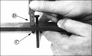
5. Loosen wing nut (C). Set height-of-cut by measuring from the top of the gauge to the bottom of the head of the bolt (D). Lock wing nut (C).
6. Hook head of bolt (D) over edge of bed knife.
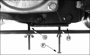
7. Loosen wing nut (E). Turn bolt (F) until gauge is parallel with bed knife. Measure distance between front (G) and rear (H) of the bottom of the bed knife to top of gauge. Distance should be the same.
NOTE: Be sure bolt (F) is not on mounting screw for bed knife.
IMPORTANT: Avoid damage! Do not turn nuts beyond where the roller just touches the gauge bar or the gauge bar will bend. |
NOTE: When adjusting rollers, move both ends of roller equally, alternating from end to end. This will keep the adjusters from binding.
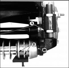
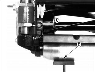
9. On grooved rollers, carefully turn bottom adjusting nut (A) until the first 2 ribs (B) of the machined portion of the roller just touches the gauge. This is determined by turning the roller and listening for the scratching sound from roller on gauge bar.
On solid rollers, carefully turn bottom adjusting nut (C) until the solid center piece of the roller (D) (not the end caps) just touches the gauge. This is determined by turning the roller and listening for the scratching sound. On rollers with scrapers, a screwdriver can be inserted in slot in scraper, lifted up, and screwdriver handle hooked under reel housing.
NOTE: Cutting units with no front roller (fixed position), set rear roller only.
10. After setting front and rear rollers on one end, lock jam nuts and recheck all gauge settings. Readjust if necessary.
11. Follow same procedure for other end of bed knife and rollers.
12. After setting second end, go back and check first settings to be sure they haven't moved. Readjust if necessary. Gauge can snugly be placed into position on either end when properly adjusted.
ADJUSTING REEL-TO-BED KNIFE CLEARANCE
This adjustment, combined with the backlapping operation, will ensure a clean cut, as well as reduce wear, take less power, and reduce down time.
Reel-to-bed knife clearance should be checked BEFORE and AFTER backlapping.
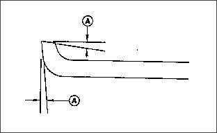
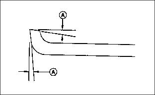
1. The cutting edge of the bed knife must be sharp and straight, and the relief angle should be 5 degrees (A) as shown.
Otherwise, remove bed knife and bed knife support and have them ground as a complete unit.
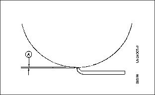
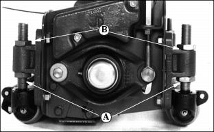
2. Use feeler gauges to set recommended reel-to-bed knife clearance (A) in the range for the grass to be cut. Finer textured grasses, such as rye grass or bent grass requires a close setting, but the setting should not be less than 0.05 mm (0.002 in.). They also require a sharp reel and bed knife to cut properly.
3. Place a 0.05 mm (0.002 in.) feeler gauge (A) between bed knife and reel. Check at both ends of reel and 2 areas near the center.
4. If adjustment is necessary, loosen jam nuts (B) and adjusting nuts (C) at both ends of the reel. Turn adjusting nuts (C) clockwise to raise reel. Turn jam nut (B) clockwise to lower reel. Adjust reel until 0.05 mm (0.002 in.) is reached across the entire reel and bed knife.
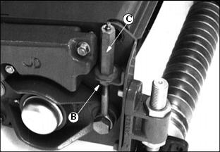
5. Tighten adjusting nuts (C) and jam nuts (B). Recheck to insure reel has not moved. Readjust if necessary.
IMPORTANT: Avoid damage! Do not allow the reel to interfere with the bed knife. Interference will cause heating and can damage reel and bed knife. |
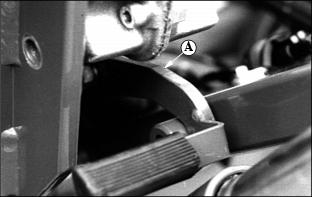
BACKLAPPING CUTTING UNITS
Backlapping cutting units must be done on a routine basis to prolong reel life, prevent downtime, and provide sharp cutting action.
IMPORTANT: Avoid damage! The reel-to-bed knife clearance should be adjusted to approximately 0.076 mm (0.003 in.) at the ends. |
1. Set parking brake on tractor and start engine.
2. Lower all cutting units to the ground.
NOTE: Do the following for each circuit - 2 on 5-gang, 3 on 7-gang.
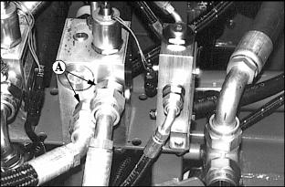
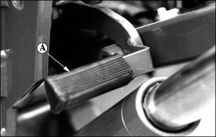
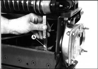
3. Reverse two hydraulic fittings (A), on each valve block,to allow cutting units to operate in reverse (backlap).
5. Adjust engine RPMs to obtain desired reel speed.
6. Reels must be turning backwards slowly enough so grinding compound will not be thrown off during backlapping.
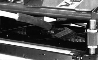
7. Using a long-handled brush, carefully apply reel sharpening compound, uniformly, from one end of REEL to other. Repeat application in opposite direction. Allow unit to continue running backwards until reel is quiet.
8. Periodically disengage PTO lever and shut engine off to visually check blade appearance.
9. Adjust reel-to-bed knife clearance by loosening jam nuts (B) and turning adjusting nuts (C) and jam nuts (B) to proper clearance on both ends. Check for uniform clearance across entire bed knife. If clearance is not uniform, repeat steps 7, 8, and 9 until clearance is uniform across entire bed knife.
10. Disengage PTO lever and shut off engine. With reel stopped, use water to thoroughly wash off all reel sharpening compound.
Backlap Valve (Optional)
An optional Backlap valve is available.
A 5-gang machine requires 2 backlap valve kits.
A 7-gang machine requires 3 backlap valve kits.
NOTE: Units will start in reverse if knob (B) is pulled out.
1. Start engine, and set the tractor throttle on low idle.
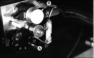
2. Position machine in backlapping mode by first pulling out on the forward/reverse knob (B). Units will start.
3. Rotate the flow control knob (A) to adjust the reel speed. Turn the knob clockwise to decrease the reel speed, counterclockwise to increase reel speed.
4. Adjust reel speed slowly enough so grinding compound will not be thrown off during backlapping.
5. Using a long handled brush, carefully apply reel sharpening compound, uniformly, from one end of the reel to the other. Repeat application in opposite direction. Allow unit to continue running backwards until reel is quiet.
6. Periodically disengage cutting units by pushing the forward and reverse knob (B) and shut off engine and visually check blade appearance
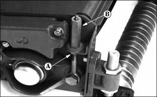
7. Adjust reel-to-bedknife clearance by loosening jam nut (A) and turning adjusting nut (B) and jam nut (A) to proper clearance on both ends. Check for uniform clearance across entire bedknife. If clearance is not uniform repeat steps 2 through 5 until clearance is uniform across entire bedknife.
8. Use water to thoroughly wash off all reel sharpening compound while reels are turning in reverse.
9. Push Forward/Reverse knob (C) in.
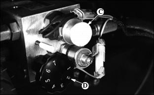
10. Shut off engine. Turn flow control knob (D) fully clockwise.
IMPORTANT: Avoid damage! Do not operate units in the forward direction until reel sharpening compound is washed from the unit. Unless properly washed, the reels can be dulled by the compound. |
READJUST REEL-TO-BED KNIFE CLEARANCE
See Adjusting Reel-to-Bed Knife Clearance in this section.
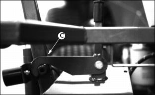
CUTTING TALLER GRASS
IMPORTANT: Avoid damage! When mowing tall grass in rough terrain, it is recommended to leave the front rollers on to protect the reels from striking any unseen objects. |
When cutting grass taller than approximately 38 mm (1-1/2 in.), the front roller tends to knock down grass affecting the quality of cut. In these conditions, it may be necessary to operate with cutting units in fixed position.
NOTE: This is recommended for smooth areas only, such as athletic fields, level parks, etc.
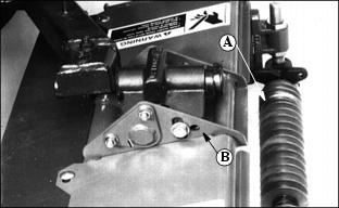
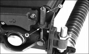
2. Remove scraper, if equipped.
3. Move cap screw, washer, and nut to fixed position (B).
GRINDING THE BED KNIFE
NOTE: Bed knife removed for illustration purposes only.
When grinding the bed knife, it is important to have a 5 degree relief angle on the top surface (A) and front surface (A).
REPLACING BED KNIFE
1. Remove 6 cap screws (A) attaching bed knife support to cutting unit housing, 3 on each end.
2. Remove bed knife support, with bed knife attached, from cutting unit housing.
3. Remove and discard screws and nuts attaching bed knife to support. Discard bed knife.
4. Remove debris, corrosion, and rust from bottom surface of bed knife support.
5. Install both end screws (B) first, snug only. This will locate the bed knife.
6. Install rest of screws and nuts.
7. Torque nuts to 1/2 torque, approximately 26 N·m (19 lb-ft.), starting from the center out in both directions.
8. Finish torquing to full torque, 51 N ·m (38 lb-ft.), starting from the center out. Minimum torque is 45 Nm (33 lb-ft.).
9. Put bed knife support and bed knife in a suitable grinder and grind until material is removed from the entire top surface of the bed knife lip.
10. Raise the reel at least 13 mm (1/2 in.) by turning the reel adjusting nut (E) clockwise and nut (D) counterclockwise.
11. Reinstall the bed knife support assembly, just snug cap screws (A).

12. Tap both ends of bed knife (C) towards reel with a brass hammer to remove any play in bed knife support. Tighten cap screws to 43 Nm (32 lb-ft.).
13. Set the height-of-cut. See Adjusting Height-of-Cut in this section.
14. Adjust the reel-to-bed knife. See Adjusting Reel-to-Bed Knife in this section.
15. Backlap reel. See Backlapping Cutting Units in this section.
16. Check the height-of-cut and adjust as necessary. See Adjusting Height-of-Cut in this section.
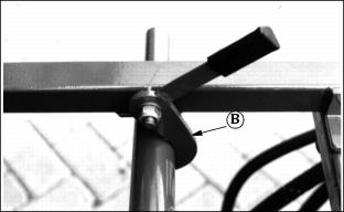
Mercury Switches
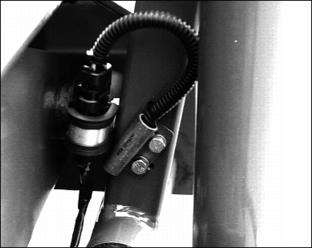
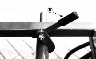
A mercury switch (A) is located on each of the lift arms. The switches cause the cutting units to stop rotating when the lift arms are raised.
Basics of Mowing Operation
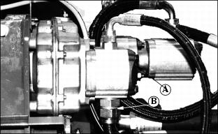
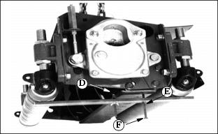
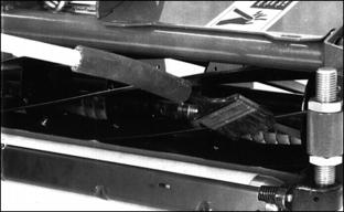
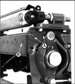
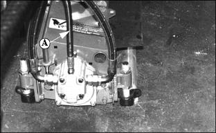
Power Take Off (P.T.O.) is attached to the gear case. One tandempump (A) (5-gang standard) is mounted on gear case, right hand connection. Left hand connection is covered with a shield.
A suction hose (B) (7-gang option shown) is installed between reel drive pump and hydraulic reservoir.
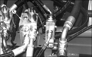
The pump provides pressure for the two mowing circuits. Each circuit is operated by electrically activated valves (C) (7-gang shown).
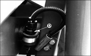
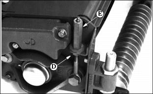
Operating of the valves takes place by means of Mercury switches (D). Each of the lift arms has one Mercury switch.
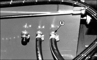
Motor drain lines from the reel motors (A) are connected directly to the reservoir ports (B).
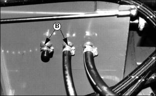
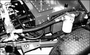
Return oil runs from the valves through the union cross (C), through the return line filter into the reservoir.
Lifting Cutting Units
Lifting takes place by means of the hydraulic circuit of the tractor. (See tractor operating section of the appropriate model tractor. These tracotrs require circuits with float detent position.)
Lift arms can be secured in raised or transport position by engaging the latches.