![]()
Introduction
Safety Signs
Operational Decals (Electro-hydraulic Option)
Operational Decals (Electro-hydraulic Option)
Controls
Installing Mower
Operating the Mower
Replacement Parts
Optional Equipment
Service Machine Safely
Service Intervals
Service Mower
Service Miscellaneous
Service Technical
Troubleshooting
Storage
Assembly
Specifications
John Deere Quality Statement

Safety Signs
Safety-Alert Symbol
Read and recognize safety information. Be alert to the potential for personal injury when you see this safety-alert symbol.
On your machine safety labels, the words DANGER, WARNING, and CAUTION are used with this safety-alert symbol. DANGER identifies the most serious hazards. In this manual, the word CAUTION and this symbol call attention to safety messages.
Machine Safety Labels
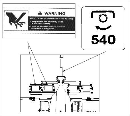

Decal (A) is a PTO entanglement decal warning that care is to be heeded when working near the PTO shaft and that the PTO should be disengaged and engine shut off when working in that area.
Decal (B) is to alert users of the gang mower that they should read the manual before operating or servicing the machine.
Operational Decals (Electro-hydraulic Option)
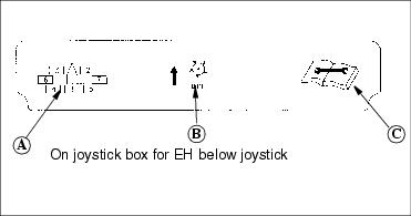
This is a general reference decal. (A) (Used on the 5 & 7 gang Electro-hydraulic option) indicates the positioning of the cutting units. (B) indicates that pushing up on any of the control box levers will raise the cutting units. (C) indicates to read the operator's manual.
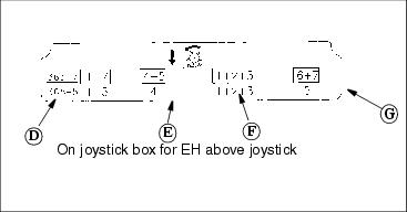
Another decal on the joystick box gives operating directions, (Also an option for the 5 & 7 gang Electro-hydraulic configuration). The top line of (D) shows that pulling the lever down engages all the cutting units in a 7-gang configuration, if the other 3 levers are down in detent position. The bottom line of (D) indicates a 5-gang EH and will lower five cutting units if that option is chosen.
Letter (E) shows which cutting units can be lowered and reels engaged depending on the option chosen. Top line for units 4 &5, for a 7-gang and bottom line for a 5-gang cutting unit 4.
Operational Decals (Electro-hydraulic Option)

Picture Note: The joystick in (D) position must be in the down or detent position to operate other levers individually.
Letter (F) shows which cutting units can be lowered and reels engaged. The top line, for a 7-gang configuration and the bottom line for a 5 gang EH configuration will engage cutting units 1-2-3.
Letter (G) shows which cutting units can be lowered and reels engaged. The top line with lower and engage reels 6 & 7 in a 7-gang option. The bottom line will lower and engage reel 5 in the 5-gang EH option.