![]()
Introduction
Safety Signs
Controls
Installing Mower
Operating the Mower
Replacement Parts
Optional Equipment
Service Machine Safely
Service Intervals
Service Mower
Service Miscellaneous
Service Technical
FLAT FACE O-RING SEAL FITTINGS
METRIC BOLT AND CAP SCREW TORQUE VALUES
METRIC BOLT AND CAP SCREW TORQUE VALUES (Continued):
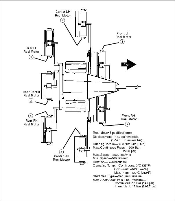
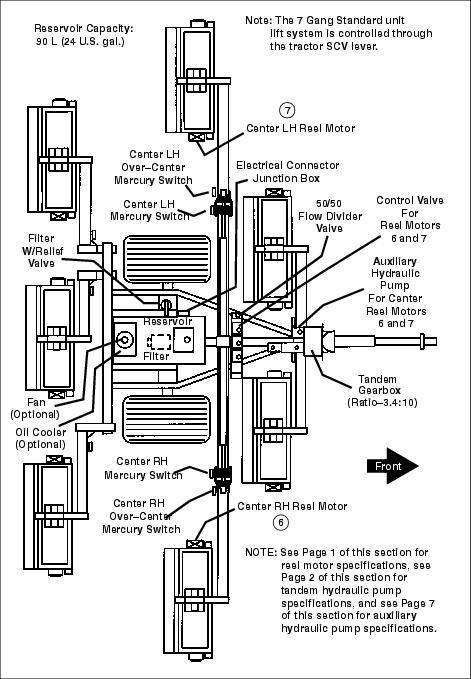
5 AND 7 GANG REEL MOTOR LOCATIONS AND SPECIFICATIONS
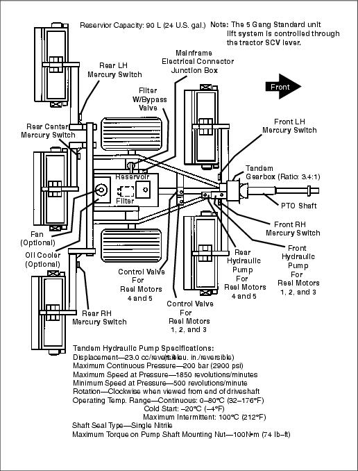
5 GANG STANDARD COMPONENT LOCATIONS AND SPECIFICATIONS
5 GANG STANDARD ELECTRICAL SCHEMATIC
5 GANG STANDARD HYDRAULIC SCHEMATIC
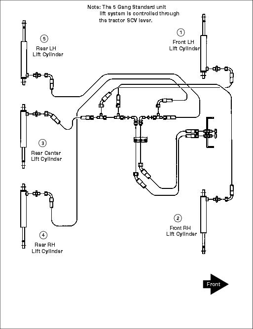
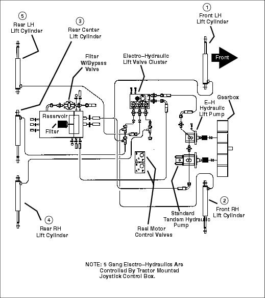
5 GANG STANDARD HYDRAULIC LIFT CIRCUIT
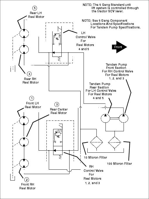
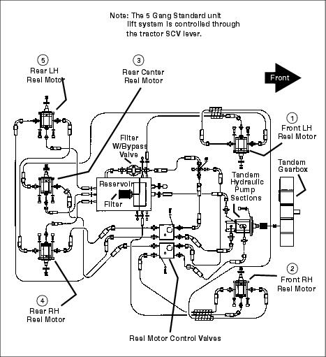
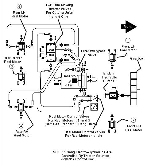
5 GANG STANDARD HYDRAULIC REEL MOTOR CIRCUIT
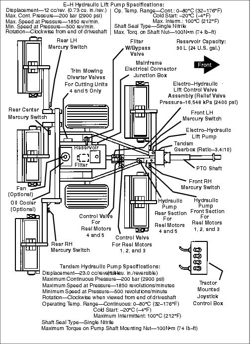
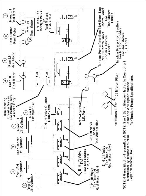
5 GANG ELECTRO-HYDRAULIC (E-H) COMPONENT LOCATIONS AND SPECIFICATIONS
5 GANG ELECTRO-HYDRAULIC (E-H) ELECTRICAL SCHEMATIC
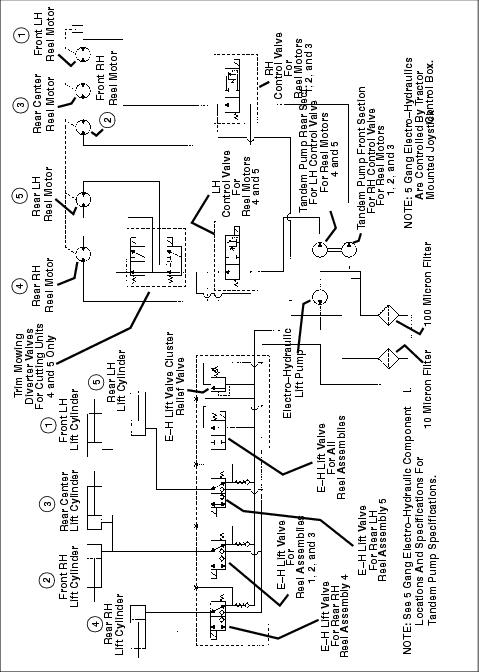
5 GANG ELECTRO-HYDRAULIC (E-H) HYDRAULIC SCHEMATIC
5 GANG ELECTRO-HYDRAULIC (E-H) HYDRAULIC SCHEMATIC WITH BACK-LAP VALVE OPTION
5 GANG ELECTRO-HYDRAULIC (E-H) HYDRAULIC LIFT CIRCUIT
5 GANG ELECTRO-HYDRAULIC (E-H) TRIM MOWING REEL MOTOR CIRCUIT - REAR REEL UNITS 4 AND 5 ONLY
7 GANG STANDARD COMPONENT LOCATIONS AND SPECIFICATIONS
7 GANG STANDARD ELECTRICAL SCHEMATIC
7 GANG STANDARD HYDRAULIC SCHEMATIC
7 GANG STANDARD HYDRAULIC LIFT CIRCUIT
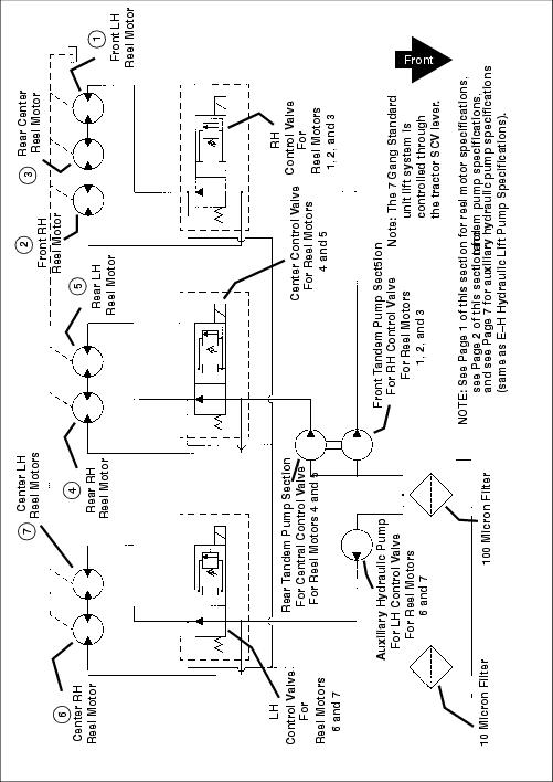
7 GANG STANDARD HYDRAULIC REEL MOTOR CIRCUIT
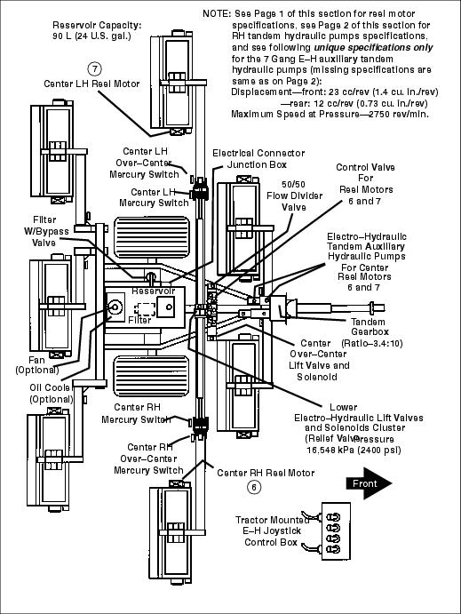
7 GANG ELECTRO-HYDRAULIC (E-H) COMPONENT LOCATIONS AND SPECIFICATIONS
7 GANG ELECTRO-HYDRAULIC (E-H) ELECTRICAL SCHEMATIC WITH OPTIONAL OIL COOLER AND FAN
7 GANG ELECTRO-HYDRAULIC (E-H) HYDRAULIC SCHEMATIC
7 GANG ELECTRO-HYDRAULIC (E-H) HYDRAULIC SCHEMATIC WITH BACK-LAP VALVE OPTION
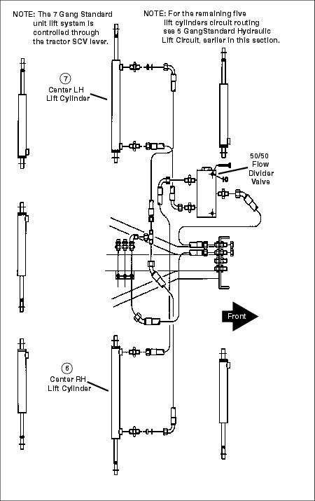
7 GANG ELECTRO-HYDRAULIC (E-H) HYDRAULIC LIFT CIRCUIT
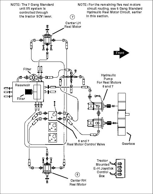
7 GANG ELECTRO-HYDRAULIC (E-H) HYDRAULIC REEL MOTOR CIRCUIT
5 AND 7 GANG OPTIONAL OIL COOLER HYDRAULIC CIRCUIT
Troubleshooting
Storage
Assembly
Specifications
John Deere Quality Statement

Service Technical
O-RING BOSS FITTINGS
1. Inspect O-ring boss seat for dirt or defects.
2. Lubricate O-ring with petroleum jelly. Place electrical tape over threads to protect O-ring. Slide O-ring over tape and into O-ring groove of fitting. Remove tape.
3. Tighten fitting to torque value shown on chart.
1. Back-off locknut and back-up washer completely to head-end of fitting.
2. Turn fitting into threaded boss until back-up washer contacts face of boss.
3. Turn fitting head-end counterclockwise to proper index (maximum of one turn).
4. Hold fitting head-end with a wrench and tighten locknut and back-up washer to proper torque value.
5. Do not allow hoses to twist when tightening fittings.
NOTE: Torque tolerance is 10%.
FLAT FACE O-RING SEAL FITTINGS
1. Inspect the fitting sealing surfaces. They must be free of dirt or defects.
2. Inspect the O-ring. It must be free of damage or defects.
3. Lubricate O-rings and install into groove using petroleum jelly to hold in place.
4. Push O-ring into the groove with plenty of petroleum jelly so O-ring is not displaced during assembly.
5. Index angle fittings and tighten by hand pressing joint together to ensure O-ring remains in place.
6. Tighten fitting or nut to torque value shown on the chart per dash size stamped on the fitting.
NOTE: Do not allow hoses to twist when tightening fittings.
NOTE: Torque tolerance is +15%-20%.
METRIC BOLT AND CAP SCREW TORQUE VALUES

METRIC BOLT AND CAP SCREW TORQUE VALUES (Continued):
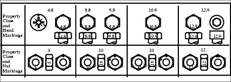
Fasteners should be replaced with the same or higher grade. If higher grade fasteners are used, these should only be tightened to the strength of the original. Make sure fasteners threads are clean and that you properly start thread engagement. This will prevent them from failing when tightening. Tighten plastic insert or crimped steel-type lock nuts to approximately 50 percent of the dry torque shown in the charts, applied to the nut, not to the bolt head. Tighten toothed or serrated-type lock nuts to the full torque value.
a "Lubricated" means coated with a lubricant such as engine oil, or fasteners with phosphate and oil coatings. "Dry" means plain or zinc plated without any lubrication. b Grade "2" applies for hexcap screws (not hex bolts) up to 152 mm (6 in.) long. Grade "1" applies for hex cap screws over 152 mm (6 in.) long, and for all other types of bolts and screws of any length.
Unified Inch Torque Values
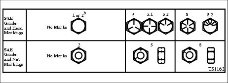
Fasteners should be replaced with the same or higher grade. If higher grade fasteners are used, these should only be tightened to the strength of the original. Make sure fasteners threads are clean and that you properly start thread engagement. This will prevent them from failing when tightening. Tighten plastic insert or crimped steel-type lock nuts to approximately 50 percent of the dry torque shown in the charts, applied to the nut, not to the bolt head. Tighten toothed or serrated-type lock nuts to the full torque value.
a "Lubricated" means coated with a lubricant such as engine oil, or fasteners with phosphate and oil coatings. "Dry" means plain or zinc plated without any lubrication. b Grade "2" applies for hexcap screws (not hex bolts) up to 152 mm (6 in.) long. Grade "1" applies for hex cap screws over 152 mm (6 in.) long, and for all other types of bolts and screws of any length.
TROUBLESHOOTING HINTS
Almost all failures in the hydrostatic reel drive system will result in a marked loss of reel speed. Each individual component will have to be tested to determine if it has failed. Fluid bypassing internally in a reel motor will reduce the pressure to the other reel motors resulting in a slower cutting speed. A weak hydrostatic pump will also result in a slower reel speed, making it almost impossible to determine what component has failed from observation alone.
Testing the hydraulic pumps with a flow tester can confirm or eliminate it as the source of the problem. This however takes time and maybe some other components should be looked at first.