![]()
Introduction
Safety Signs
Controls
Installing Mower
Operating the Mower
Replacement Parts
Optional Equipment
Service Machine Safely
Service Intervals
Service Mower
Service Miscellaneous
Adapter Piece For Jackstand (optional)
Service Technical
Troubleshooting
Storage
Assembly
Specifications
John Deere Quality Statement

Service Miscellaneous
Checking Tire Pressure
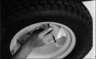
2. Check tire pressure with an accurate gauge.
Adapter Piece For Jackstand (optional)
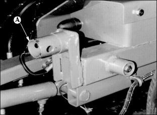
Remove cap from frame and place the adaptor into the frame (A).
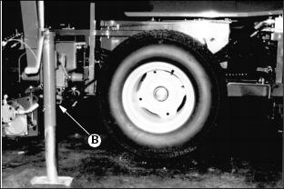
Release the jackstand (B) from the mower hitch and attach it to the adapter (A). Lock in place with the pin.
Jack up the mower and take off the wheel.
Replace with new or repair wheel assembly and replace jack in normal storage position.
NOTE: DO NOT leave adaptor in frame when not in use.
Electrical
This machine can have an optional 5 or 7 gang electro-hydraulic lift configuration. (See the instruction sheets that come with the corresponding option, Electrical and hydraulic schematics enclosed in the manual).
NOTE: Base machine has electrical reel shutoff only, no electro-hydraulic lift.
Electrical Plug Sockets
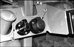
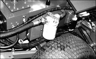
Install plug socket on a suitable place at the backside of the tractor (A).
Connect the brown wire with the ground (-) wire of the tractor. Connect the red (+) wire with the ignition lock via a fuse.
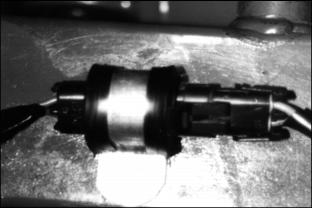
Connect the plug from mower cable (B) with plug socket.
The tandem hydraulic pump provides pressure for the two mowing circuits. Each circuit is operated by electrically activated solenoid reel control valves.
Operating the valves takes place by means of Mercury switches. Each lift arm has one Mercury switch which open or close the electro circuits to turn on or off the solenoid valves controlling oil flow in the reel circuits.
Electrical Routing
Connect the Mercury switches with the plugs of wiring harness (B).
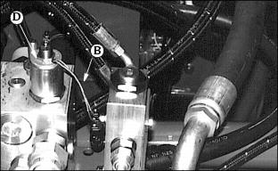
Connect the plug of wire harness with the plug of the univalve (D) or backlap valve.
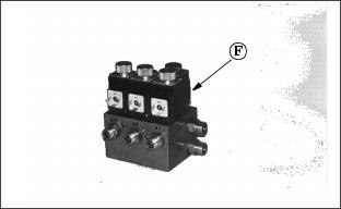
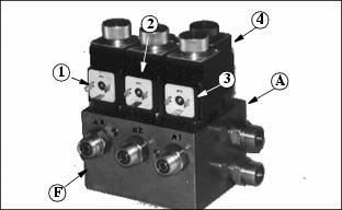
If optional electrohydraulic lift package installed, attach harness to main harness and solenoids on EH lift valve (F).
Now take the wiring diagram (See Technical section).
Fit the plugs onto the valve block (F) as follows:
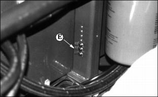
All ground connectors (E), relays and harness connector blocks are located under cover (A) prior page.
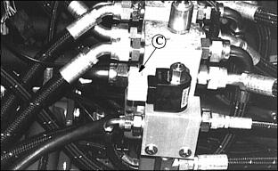
Connect wire harness (C) for a 7-gang EH valve to over-center valve on unit to lower cutting units.