![]()
Introduction
Product Identification
Safety
Operating Machine
Operating Mower Deck - 1600
Replacement Parts
Service Intervals
Service Lubrication
Service Engine
Service Transmission
Service Steering & Brakes
Service Mower Deck - 1600
Removing and Installing Belt Shields
Adjusting Mower Deck Drive Belt Tension
Removing and Installing Front Mower Deck Drive Belt
Removing and Installing Side Mower Deck Drive Belt
Removing and Installing Blades
Service Electrical
Service Miscellaneous
Troubleshooting
Storage
Assembly - 1620
Specifications
Warranty
John Deere Quality Statement
Service Record
Copyright© Deere & Company

Service Mower Deck - 1600
Rotating the Front Mower Deck
Rotate for Service
1. Stop machine on a level surface.
3. Raise front mower deck completely.
4. Stop engine and remove the key.
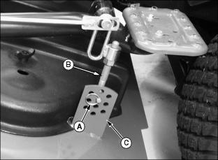
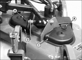
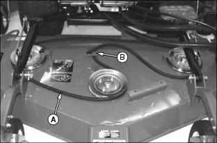
5. Remove retaining ring (A) from hanger pin (B).
NOTE: To ensure deck can be returned to its original cutting height, note hole location in the adjustment plate before removing the hanger pin.
6. Remove hanger pin from hole in adjustment plate (C).
7. Install retaining ring to hanger pin for temporary storage.
8. Repeat at opposite side of mower deck.
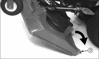
9. Grasp deck handle (D) and rotate mower deck rearward to the ground.
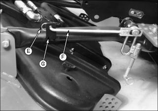
10. Remove retaining ring (E) from service lockout rod (F).
11. Remove service lockout rod from mower lift arm (G).
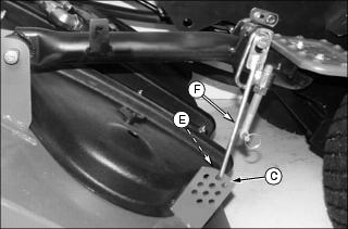
12. Insert service lockout rod into hole in deck height adjustment bracket (C). Secure with retaining ring.
13. Repeat at opposite side of mower deck.
Rotate for Operation
1. Remove retaining ring from service lockout rod.
2. Remove service lockout rod from hole in deck height adjustment bracket.
3. Insert service lockout rod into hole in mower lift arm. Secure with retaining ring.
4. Repeat at opposite side of mower deck.
5. Remove retaining ring from hanger pin.
7. Insert hanger pin into original hole in adjustment plate. Secure with retaining pin.
8. Repeat at opposite side of mower deck.
10. Lower front mower deck completely.
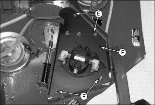
Removing and Installing Belt Shields
Front Deck Shields
1. Rotate front mower deck for service. Do not secure service lockout rods (A) to the adjustment plates.
2. Remove threaded knobs (B) securing belt shields (C) and (D) to mower deck.
3. Lift each belt shield up off of the attaching bolts. Slide shields out from between mower lift arms (E) and mower deck.
4. Install the threaded knobs onto the attaching bolts during servicing of the deck.
5. Installation is the reverse of removal.
6. Rotate mower deck for operation.
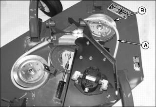
Side Deck Shields
1. Park machine safely. (See Parking Safely in Safety section.)
2. Remove threaded knobs (A) securing belt shields (B) and (C).
3. Lift each belt shield up off of the attaching bolts.
4. Install the threaded knobs onto the attaching bolts during servicing of the deck.
5. Installation is the reverse of removal.
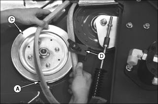
Adjusting Mower Deck Drive Belt Tension

Picture Note: Front deck shown upper, side deck shown lower.
1. Remove belt shield (A) from mower deck.

Picture Note: Front deck shown, side deck similar.
4. Loosen lock nut (D) several turns.
5. Tighten nut (E) until tension indicator hole (F) becomes visible on the outside of retaining plate (G) as shown.
7. Tighten nuts (B) and (C) to 60 N·m (81 lb-ft).
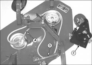
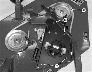
Removing and Installing Front Mower Deck Drive Belt
Front Belt Removal
1. Remove belt shields from mower deck.
2. Lower mower deck completely.
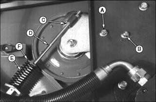
4. Loosen nut (C) until all spring tension is removed.
5. Remove tension rod (D), spring (E), and spring retainer (F).
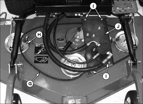
6. Remove drive belt (G) from sheave (H).
7. Remove bolts (I) from motor plate (J).
8. Slide motor plate (J) rearward so sheaves on bottom side clear motor plate mounting brackets (K).
9. Lift motor plate off mounting brackets and set it aside.
10. Remove drive belt (G) from deck.
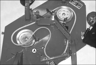
Front Belt Installation
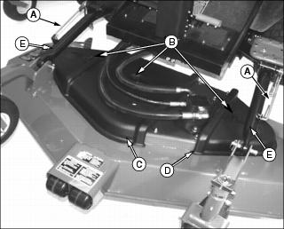
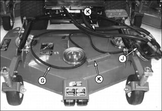
NOTE: Belt routing diagram is affixed to mower deck.
1. Route drive belt (A) around mower deck sheaves as shown. Place belt to the outside of belt shield support bracket (B) to temporarily hold the belt in position.
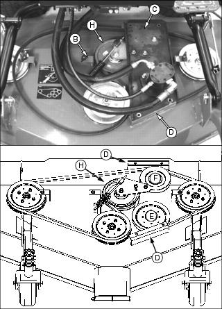
2. Position motor plate (C) onto motor plate mounting brackets (D) so drive belt is routed properly around sheaves (E) and (F).
3. Move the drive belt from outside belt shield support bracket (B), and position it around tension sheave (H).
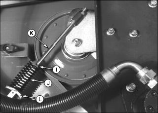
4. Make sure spring retainer (I) and spring (J) are installed on tension rod (K). Insert tension rod into retaining plate (L) on mower deck.
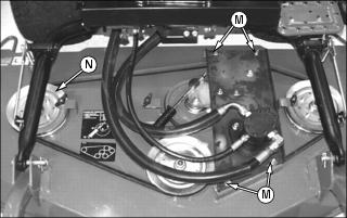
5. Install bolts (M) to secure motor plate. Do not tighten completely.
6. Install drive belt onto sheave (N).
7. Tighten bolts (M) to 81 N·m (60 lb-ft).
8. Adjust drive belt to proper tension.
9. Move the drive belt by hand to turn the sheaves. Make sure belt motion is smooth and sheaves do not rub on deck surfaces.
Removing and Installing Side Mower Deck Drive Belt
Side Belt Removal
1. Lower mower deck completely.
2. Remove belt shields from mower deck.
3. Release the drive belt tension completely.
Picture Note: Mower deck shown removed for clarity.
4. Remove drive belt (A) from sheave (B).
5. Remove drive belt (A) from sheave (C) by twisting the belt and sliding it between belt shield support bracket (D) and the sheave.
6. Remove bolts (E) from motor plate (F).
7. Slide motor plate (F) forward so sheave on bottom side clears motor plate mounting bracket (G).
8. Lift motor plate off mounting brackets and set it aside.
9. Remove drive belt (A) from deck.
Side Belt Installation
NOTE: Belt routing diagram is affixed to mower deck.
1. Route drive belt (A) as shown.
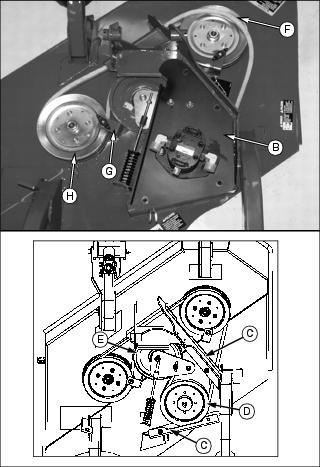
2. Position motor plate (B) onto motor plate mounting brackets (C) so drive belt is routed properly around sheaves (D) and (E).
3. Remove drive belt from sheave (F).
4. Slide drive belt between belt shield support bracket (G) and sheave (H). Ensure proper positioning of belt in the belt grooves.
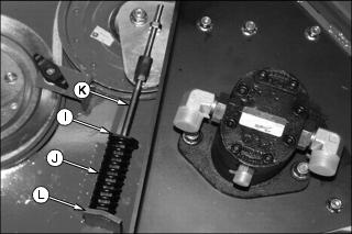
5. Make sure spring retainer (I) and spring (J) are installed on tension rod (K). Insert tension rod into retaining plate (L) on mower deck.
6. Install bolts (M) to secure motor plate. Do not tighten completely.
7. Install drive belt onto sheave (F).
8. Tighten bolts (M) to 81 N·m (60 lb-ft).
9. Adjust drive belt to proper tension.
10. Move the drive belt by hand to turn the sheaves. Make sure belt motion is smooth and sheaves Do not rub on deck surfaces.
Removing and Installing Blades
1. Stop machine on a level surface.
3. Raise mower decks completely.
4. Stop engine and remove the key.
5. Rotate front mower deck for service if blades on front deck will be removed.
6. Insert wooden block between end of blade and edge of deck to prevent blade from turning while removing attaching hardware.
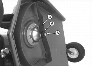
7. Remove bolt (A), washer (B), and blade (C) by turning the bolt counterclockwise until removed. Repeat for all blades requiring service.
8. Inspect the blades for damage. Replace all damaged blades.
10. Clean blades, spindles, and hardware.
12. Install blade onto mower deck spindle with wings of blade facing up.
13. Install blade bolt and washer with the cupped-side of washer against the blade. Tighten blade bolt to 122 N·m (90 lb-ft). Repeat for other blades.
14. Lower mower decks completely.
Sharpening Blades
1. Sharpen blades with grinder, hand file, or electric blade sharpener.
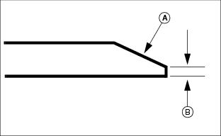
2. Keep original bevel of 30° (A) when grinding blade. Blade should have 0.40 mm (1/64 in.) cutting edge (B).
Balancing Blades
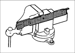
2. Put the blade on a nail secured in a vise or wall. The heavy end of the blade will drop.
3. Grind the bevel of the heavy end. Do not change the bevel.