![]()
Introduction
Product Identification
Safety
Operating Machine
Operating Mower Deck - 1600
Replacement Parts
Service Intervals
Service Lubrication
Service Engine
Service Transmission
Service Steering & Brakes
Service Mower Deck - 1600
Service Electrical
Service Miscellaneous
Troubleshooting
Storage
Assembly - 1620
Specifications
Warranty
John Deere Quality Statement
Service Record
Copyright© Deere & Company

Operating Mower Deck - 1600
Adjusting Cutting Height
1. Stop machine on level surface, PTO off, park brake locked.
2. Raise all mower decks. Engage left and right side deck transport locks. Stop engine.
3. Check tire pressures on all machine tires, and deck caster wheels.
· Machine front tires: 140 kPa (20 psi)
· Machine rear tires: 140 kPa (20 psi)
· Mower deck caster wheels: 275 kPa (40 psi)
Adjusting Front Deck Cutting Height
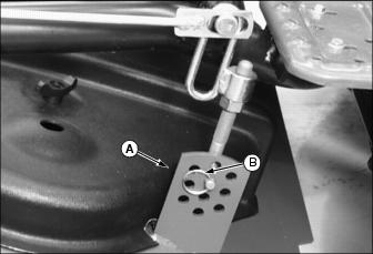
1. Remove retainer ring (A) from deck hanger pin (B) on left and right side of front deck.
2. Using the figure above, or decal mounted on front deck, place deck hangers into holes that match desired cutting height.
3. Install retainer rings into hanger pins.
4. Adjust caster wheels on front deck to match cutting height selected on hanger.
Adjusting Caster Wheels Cutting Height
NOTE: This adjustment is for all caster wheels on front and side mower decks.
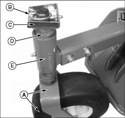
2. Support the caster wheel and bracket (A) with one hand, while removing quick-lock pin (B) and spacer guard (C).
3. Remove the spacers (D) from the top of the caster pivot shaft.
4. Lower the caster and pivot shaft out of the caster support bracket (E).
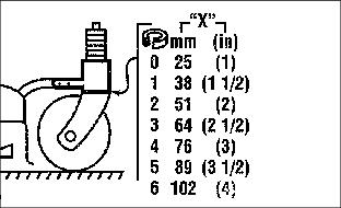
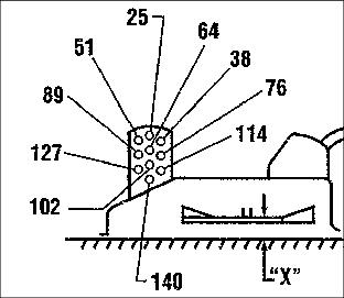
5. Use the figures above, or decal mounted on front mower deck to select the number of spacers needed to set caster wheel to desired height.
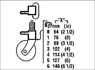
6. Flip caster support brackets over to adjust blades to higher than 102 mm (4 in.) cutting height.
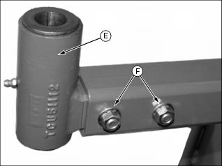
· To flip the caster support brackets (E), remove two cap screws, nuts, and bushings (F), holding support bracket to mower deck arm. Remove bracket from arm, flip over bracket, and install back into arm.
7. Install cap screws and nuts, but do not tighten nuts at this time.

8. Install the proper number of spacers (F) onto the caster shaft.
9. Install the caster wheel and bracket (G) up though the caster support bracket (H).
10. Install remaining spacers (I) onto the top of the caster shaft.
NOTE: When adjusting side decks to 25 mm (1 in.) height of cut, do not install spacer guard (J) on inside caster wheel pivot. Spacer guard may contact engine cover when side deck is raised.
11. Install the spacer guard (J) with open end facing forward (as shown).
12. Install quick-lock pin (K) into caster shaft and hole in spacer guard. Snap retainer loop over caster shaft.
13. If cutting height was adjusted above 102 mm (4 in.), perform the follow steps:
a. Lower mower deck to ground.
b. Turn caster wheels so they are trailing to the rear (as would happen during normal forward travel).
c. Tighten caster support bracket hardware.
Checking Mower Deck Level
1. Park machine safely. (See Parking Safely in the SAFETY section.)
2. Lower all mower decks completely to ground.
3. Check tire pressures on all machine tires, and deck caster wheels.
· Machine front tires: 140 kPa (20 psi)
· Machine rear tires: 140 kPa (20 psi)
· Mower deck caster wheels: 275 kPa (40 psi)
4. Set the mower decks at the desired cutting height.
5. Check that the front mower deck caster wheels and rear hangers are all set to the same height.
6. Check that all caster wheels are trailing towards the rear, as they would be during normal forward travel.
7. Turn the blades until parallel to the front axle.

Picture Note: A convenient leveling gauge (A) is available from your John Deere dealer that will slip under the lip of the deck and measure blade height.
8. Measure distance from tip of outside blade (B), to the ground. Repeat for blade on other side of deck. Mower blades should be level on both sides of deck.
9. Turn outer mower blades to face front-to-rear.
10. Measure height of front and rear of outer blade to ground. Repeat for other side.
· The blade cutting heights should be level side-to-side.
· The rear tips of the blades should be 6mm (0.25 in.) higher than the front blade tips.
Adjusting Mower Deck Level
1. Park machine safely. (See Parking Safely in the SAFETY section.)
2. Lower all mower decks completely to ground.
3. Check tire pressures on all machine tires, and deck caster wheels.
· Machine front tires: 140 kPa (20 psi)
· Machine rear tires: 140 kPa (20 psi)
· Mower deck caster wheels: 275 kPa (40 psi)
4. Set the mower decks at the desired cutting height.
5. Turn all caster wheels so they are trailing to the rear (as would happen during normal forward travel).
Adjusting Front Mower Deck Level
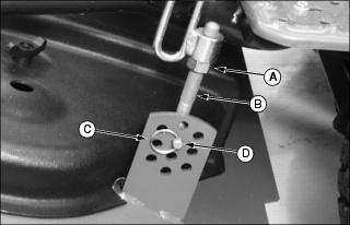
1. Loosen lock nut (A) on deck hanger (B).
2. Remove retainer ring (C) on hanger pin (D).
3. Turn rear hanger up or down to adjust deck height until blades are level side-to-side and front-to-rear.
4. Insert hanger pin (D) back into proper height adjuster hole, and secure with retainer ring.
NOTE: It may be necessary to reduce caster wheel air pressure on one side only to help level mower deck.
Adjusting Side Mower Deck Level
The side mower deck level can be adjusted by lowering the air pressure in the two caster wheels on the side which is high. Do not exceed recommended air pressure in tires.
Engaging Blades
NOTE: Operate engine at full throttle while mowing.
2. Move speed range lever to the low speed range position.
4. Lower mower decks to ground.
5. Move throttle forward to full throttle position.
6. Pull up on PTO switch lever and move switch to the on position.
· Blades should start and PTO indicator lights should light up.
· If one side deck is not lowered, the indicator light for that deck will flash, and blades for that deck will not start up until deck is lowered.
· If front deck is not lowered, none of the blades will start up.
7. Raise decks to disengage blades:
· If a side deck is raised while mowing, the blades for that deck will stop when it is raised, and the PTO indicator light for that deck will flash. Blades will start up again once the deck is lowered.
· If the front deck is raised while mowing, all blades on all decks will stop. Once front deck is lowered, the PTO switch will have to be cycled on-off-on to restart blades.
· Move the PTO switch to the off position to stop all blades.