![]()
Introduction
Safety Signs
Controls
Operating
Lawn Care
Replacement Parts
Service Machine Safely
Service Intervals
Service Engine
Changing Engine Oil And Filter
Checking Air Restriction Indicator
Cleaning Air Intake Screen And Radiator
Cleaning And Gapping Spark Plugs
Service Transmisson
Service Steering & Brakes
Service Electrical
Service Miscellaneous
Troubleshooting
Storing Vehicle
Assembly
Specifications
Warranty
John Deere Quality Statement
Copyright© Deere & Company

Service Engine
Avoid Fumes
· If it is necessary to run an engine in an enclosed area, use an exhaust pipe extension to remove the fumes. |
Engine Oil
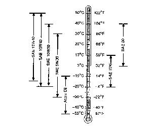
Use oil viscosity based on the expected air temperature range during the period between oil changes.
The following oil is preferred:
Other oils may be used if they meet one the following:
· API Service Classification SG
· API Service Classification SF
Oils meeting Military Specification MIL-L-46167B may be used as arctic oils.
Checking Engine Oil Level
1. Park Front Mower on a level surface.
2. Check engine oil when oil is cold.
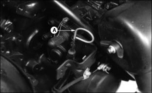
4. Remove dipstick (A). Wipe dipstick with a clean rag.
6. Remove dipstick. Check oil level on dipstick.
7. Oil must be between FULL mark "H" and LOW mark "L" on dipstick.
8. If oil level is low, remove oil filler cap.
9. Add oil to bring oil level no higher then the "F" mark on dipstick. (See ENGINE OIL in this section for correct oil.)
11. Install and tighten oil filler cap.
Changing Engine Oil And Filter
1. Park Front Mower on a level surface.
2. Run engine a few minutes to warm oil.
6. Remove drain plug. Drain oil in pan.
7. While oil is draining, change oil filter.
9. Put a drain pan under filter (A).
10. Remove filter using a filter wrench. Turn filter counterclockwise.
11. Apply a film of clean engine oil on seal of new filter.
12. Install filter. Turn filter until seal contacts mounting surface. Then turn filter BY HAND 1/2 turn more.
13. Install and tighten drain plug.
14. Remove filler cap. Add approximately 2.3 L (2.5 qt) of oil. (See Engine Oils in this section for correct oil.)

15. Remove dipstick (B) to check oil level. Add oil only to mark "H" on dipstick.
NOTE: Mark "L" is low oil level on dipstick.
17. Start engine and run at slow speed for 2 minutes. Check for leaks around filter and drain plug.
18. STOP engine. Check oil level.
19. Install dipstick. Lower hood.
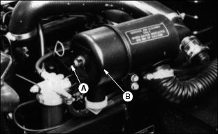
Checking Air Restriction Indicator
· DO NOT replace primary element unless air restriction indicator shows 635 mm (25 in) vacuum.
· DO NOT replace secondary element unless air restriction indicator shows 500 mm (20 in) vacuum after primary element is replaced.
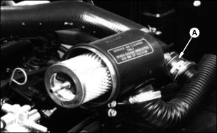
· It is normal for air restriction indicator (A) to show at least 380 mm (15 in) vacuum after primary element is replaced.
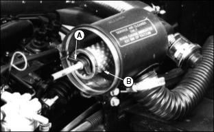
Cleaning Air Intake Screen And Radiator
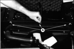
2. Loosen three wing nuts (A) to remove screen.
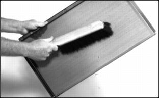
3. Clean screen with a brush or compressed air.
4. Clean air intake screen and radiator cooling fins using compressed air or a brush.

Service Cooling System Safely
Engine Coolant
Use ethylene glycol base coolant. These coolants usually have labels stating "For Automobile and Light Duty Service." These products are also often labeled for use in aluminum engines. Check container label before using.
IMPORTANT: Avoid damage! To prevent engine damage, DO NOT use pure antifreeze or more than 50% antifreeze in the cooling system. DO NOT mix or add any other type additives to the cooling system. |
Mix approximately 50 percent antifreeze with 50 percent distilled or deionized water. This mixture will provide freeze protection to -37 degrees C (-34 degrees F).
Certain geographical areas may require lower temperature protection. See the label on your antifreeze container or consult your John Deere dealer to obtain the latest information and recommendations.
The recommended antifreeze provides:
· Corrosion-resistant environment within the cooling system.
· Compatibility with cooling system hose and seal material.
· Protection during cold and hot weather operations.
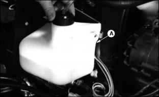
Checking Coolant Level
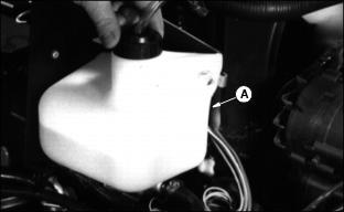
2. Coolant level must be 25-51 mm (1-2 in) in recovery tank (A).
3. If coolant is low, remove coolant recovery tank cap.
4. Add 50 percent ethylene glycol (without stop-leak additive) antifreeze and 50 percent water to proper level.
5. Install and tighten coolant recovery tank cap.
6. Clean debris from air intake screen and radiator. (See Cleaning Air Intake Screen And Radiator in this section.)
7. Check condition of hoses. Check for leaks or loose connections.
Draining Cooling System
· Do not remove radiator cap unless engine is cool. |
1. STOP engine. Let engine cool.
3. Slowly remove radiator cap.

4. Open radiator petcock (A). Drain coolant into a bucket.
5. Loosen block drain (B) one or two turns and drain coolant from engine block.
6. After all coolant has drained, close radiator petcock and tighten block drain.
7. Flush cooling system. (See Flushing Cooling System this section.)
Flushing Cooling System
IMPORTANT: Avoid damage! To prevent engine damage, DO NOT pour water into a hot engine. DO NOT operate engine without coolant. |

1. Fill cooling system with clean water and John Deere Cooling System Cleaner, or John Deere Cooling System Quick Flush or an equivalent. Follow directions on can.
2. Install and tighten radiator cap.
3. Start and run engine until it reaches operating temperature.
4. Drain cooling system immediately before rust and dirt settle.
6. Remove and clean recover tank (A).
7. Install tank after cleaning.
8. Fill cooling system. (See Filling Cooling System this section.)
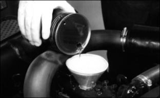
Filling Cooling System
IMPORTANT: Avoid damage! To prevent engine damage, DO NOT use straight antifreeze or more than 50% antifreeze in the cooling system. DO NOT mix or add any other type additives to the cooling system. |
· Use a solution of only low silicate ethylene glycol antifreeze (without a stop-leak additive) and clean, soft water.
· A chart on the antifreeze container tells how much antifreeze to use for freeze protection needed in your area.
2. When operating engine in extremely cold temperatures, see your John Deere dealer for information on arctic operation.
3. For temperatures above freezing, fill cooling system with clean, soft water and John Deere Engine Coolant Conditioner.
4. John Deere Cooling System Sealer or its equivalent may be added to the radiator to seal leaks. Do not use any other additives in the cooling system.
5. Install and tighten radiator cap.
6. Run engine until it reaches operating temperature.
8. After engine cools, check coolant level in recovery tank. Level should be approximately 25-51 mm (1-2 in).
9. Remove cap to add coolant, if necessary.
10. Check condition of coolant system hoses. Install new hoses, if necessary.
11. Tighten hose clamps, if necessary.
Adjusting Carburetor
NOTE: The carburetor is calibrated by the engine manufacturer and should not require any adjustments.
If engine is operated at altitudes above 1829 m
(6,000 ft.), some carburetors may require a special high altitude main jet. See your John Deere dealer.
Possible engine surging will occur at high rpm when the transmission is in neutral ("N") and the PTO switch is in the OFF position. This is a normal condition due to the emission control system.
If engine is hard to start or runs rough, check the TROUBLESHOOTING section of this manual.
After performing the checks in the troubleshooting section and your engine is still not performing correctly, contact your John Deere dealer.
Replacing Primary Element
IMPORTANT: Avoid damage! DO NOT clean primary element. · DO NOT replace primary element unless air restriction indicator shows 635mm (25 in). |
2. Remove wing nut (A) and cover (B).

3. Remove and discard wing nut and washer (C).
4. Remove and discard old primary element (D).
5. Wipe dirt from inside of cannister with a soft cloth.
6. Install new primary element.
7. Install new wing nut and washer.
9. Install old cover with washer and wing nut.
11. Depress reset button (E) on air restriction indicator (F) and then release to reset.
12. Start engine and allow it to run a minute at maximum speed.
13. STOP engine and check air restriction indicator. If indicator shows 500 mm (20 in) or more vacuum, replace secondary element.
Replacing Secondary Element
1. Remove primary element. (See Replacing Primary Element in this section.)
2. Remove wing nut (A) and secondary element (B).
3. Install new secondary element.
4. Install washer and wing nut.
IMPORTANT: Avoid damage! It is normal for air restriction indicator to show at least 380 mm (15 in) vacuum, after primary element is replaced. |

6. Install new primary element. (See Replacing Primary Element this section.)
7. Install washer and wing nut.
Cleaning And Gapping Spark Plugs
2. Disconnect spark plug wires from spark plugs.
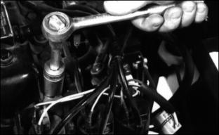
4. Clean spark plugs carefully with a wire brush.
· Pitted or damaged electrodes.
NOTE: In Canada, replace spark plugs with resistor-type plugs only.
6. Replace spark plugs as necessary.

7. Check plug gap with a wire feeler gauge.
8. Gap must be 0.76 mm ( 0.030 in.).
9. To change gap, move the outer electrode toward the center electrode.
10. Install and tighten spark plugs to 20 N·m (15 lb-ft).
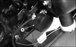
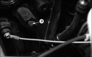
Changing Fuel Filter
NOTE: Some models fuel filter is located as shown in photo. Other models fuel filter is located under seat.
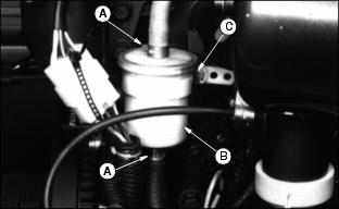
4. Loosen and slide hose clamps (A) away from filter (B).
6. Remove screw (C) to remove filter.
7. Install new filter with screw and connect hoses to filter.
8. Slide clamps against filter and tighten clamps.
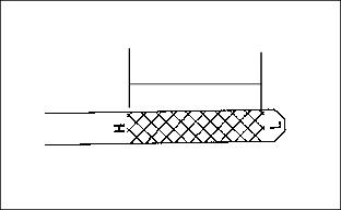
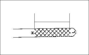
Checking PTO Belt Tension
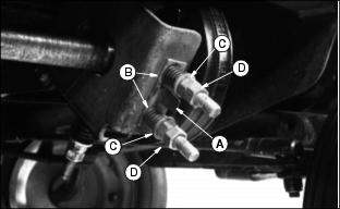
1. The end of plastic gauge (A) must be aligned with ends of springs (B) for proper belt tension.
2. Loosen nuts (C). Tighten nuts (D) equally to get proper belt tension.
3. Tighten nuts (C) against nuts (D).
4. Check PTO belts for wear damage; replace if necessary.
Grease
Use grease based on the expected air temperature range during the service interval.

The following greases are preferred:
· John Deere MOLY HIGH TEMPERATURE EP GREASE
· John Deere HIGH TEMPERATURE EP GREASE
Other greases may be used if they meet one of the following:
· SAE Multipurpose EP Grease with a maximum of 5% molybdenum disulfide
Greases meeting Military Specification MIL-G-10924F may be used as arctic grease.
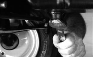
Lubricating Engine Driveshaft

Lubricate U-Joint fitting (A) with one or two shots of John Deere Multipurpose Grease or equivalent.
Lubricating PTO Shaft Bearing
IMPORTANT: Avoid damage! Check Attachment Operator Manual for servicing requirements and service at the same time as servicing the mower. |
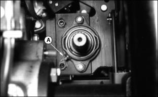
Lubricate fitting (A) on PTO shaft bearing with one or two shots of John Deere Multipurpose Grease or equivalent.