![]()
Introduction
Safety Signs
Controls
Operating
Lawn Care
Replacement Parts
Service Machine Safely
Service Intervals
Service Engine
Service Transmisson
Service Steering & Brakes
Service Electrical
Checking Battery Electrolyte Level
Service Miscellaneous
Troubleshooting
Storing Vehicle
Assembly
Specifications
Warranty
John Deere Quality Statement
Copyright© Deere & Company

Service Electrical
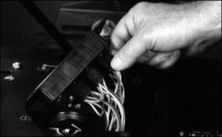
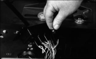
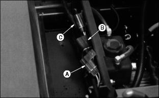
Cleaning Or Replacing Battery
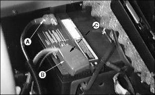
3. Disconnect black negative (-) cable (A) from battery first.
4. Open positive terminal cover (B).
5. Disconnect red positive (+) cable (C).
6. Clean battery with a damp cloth or rag. Keep dirt out of battery cells.
7. Remove corrosion from terminals and cable clamps with a wire brush.
8. If necessary, remove battery to thoroughly clean it:
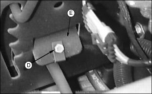
· Loosen cap screw (D) to remove battery hold-down (E).
· Disconnect overflow tube from manifold cell cap.
9. Clean battery, battery terminals, cable ends, battery box, and other parts with a solution of 1 part baking soda to 4 parts water. KEEP solution out of battery cells.
10. Rinse all parts with clean water and let dry.
NOTE: If you need a new battery, install a John Deere battery or a battery of equal specification. (See your John Deere dealer.)
11. Install battery and battery hold-down. (See Install Battery in Assembly section.)
13. Connect overflow tube to manifold cell cap.
14. Connect red positive cable (+) to battery.
15. Close positive terminal cover.
16. Connect black negative cable (-) to battery. Make sure connections are tight.
17. Apply petroleum jelly or silicone spray to terminals to prevent corrosion
Checking Battery Electrolyte Level

2. Remove battery manifold cap (A).
IMPORTANT: Avoid damage! DO NOT fill cells to the bottom of the filler neck (B). Electrolyte can overflow when battery is charged and cause damage. |
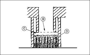
3. Electrolyte (C) should be 6 mm (1/4 in.) above plates (D).
4. If necessary, add distilled water.
Charging The Battery Safely
Follow instructions on the battery charger or in the charger operator's manual, or use the instructions below as a guide.
· Wait until the battery has warmed to room temperature. Do not charge a frozen battery.
· Check the electrolyte level of each cell. (See Checking Battery Electrolyte Level in this section.)
· Install the battery cap(s) on the battery.
Turn OFF and unplug the charger before you connect cables to the battery or disconnect cables from the battery.
If the battery becomes warm to touch during charging:
· Stop charging the battery until it cools.
Charging The Battery Safely
1. Remove and clean battery. (See Cleaning Or Replacing Battery in this section.)
2. Check electrolyte level. (See Checking Battery Electrolyte Level in this section.)
3. Leave cell caps on battery while you charge it.
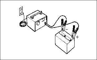
4. Connect positive (+) charger cable to positive (+) battery terminal.
5. Connect negative (-) charger cable to negative (-) battery terminal.
7. Charge battery. See Charging Rates on the next page.
8. Unplug charger cord. Remove charger cables.
Charging Rates
See your battery charger or charger operator's manual for information on charging. Or read the information below to FULLY CHARGE your battery.
For a charger with a CURRENT ADJUSTMENT CONTROL:
· Adjust the control to 10 amps.
· Charge the battery for 6-8 hours.
For a charger with a switch for MAINTENANCE FREE, DEEP CYCLE, or NORMAL (CONVENTIONAL) setting:
· Use the MAINTENANCE FREE or DEEP CYCLE setting.
For a charger with SLOW CHARGE, FAST CHARGE, or BOOST CHARGE setting:
· DO NOT use the BOOST CHARGE setting.
· Use the SLOW CHARGE setting:
-For a charger rated at less than 10 amps.
-For a charger rated at 10 amps.
NOTE: Your charger may have an AUTOMATIC STOP to prevent charging the battery:
· When the battery is fully charged OR
· When the battery is not in condition to take a charge.
Using Booster Battery
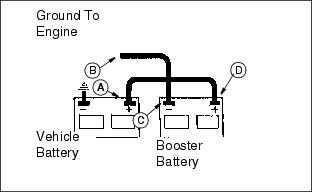
Connect positive (+) booster cable to booster battery positive (+) post (D).
Connect the other end of positive (+) booster cable to vehicle battery positive (+) post (A).
Connect negative (-) booster cable to booster battery negative (-) post (C).
Connect the other end of negative (-) booster cable to engine ground (B) away from battery.
Changing Fuses
4. Install new fuse. Make sure you have correct size and amperage.
Changing Indicator Bulb
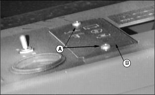
1. Remove two screws (A) to remove indicator panel (B).