![]()
Introduction
Safety Signs
Controls
Operating
Lawn Care
Replacement Parts
Service Machine Safely
Service Intervals
Service Engine
Service Transmisson
Service Steering & Brakes
Service Electrical
Service Miscellaneous
Troubleshooting
Storing Vehicle
Assembly
Checking Tire Pressure (Continued)
Specifications
Warranty
John Deere Quality Statement
Copyright© Deere & Company

Assembly
Activate Battery
IMPORTANT: Avoid damage! To prevent damage to tractor from spilled electrolyte, remove the battery from the tractor. |
1. Remove the battery from the vehicle.
2. Remove and discard tape from across battery cells.
3. Remove and discard blue cell caps.
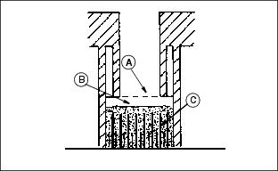
· Only use battery acid with a 1.265 specific gravity. Slowly add acid (B) to each cell. The solution should be 6 mm (1/4 in.) above plates (C), but NO HIGHER THAN 6 mm (1/4 in.)from the bottom of the filler neck (A).
5. Install the battery manifold cap from the bag of parts. Be sure manifold cap hose is behind positive cable.
6. Charge the battery for a MINIMUM of 30 minutes at 5-10 amps. If your battery charger has a Deep Cycle or Maintenance Free setting, use this setting to charge the battery. Failure to charge the battery before use will reduce battery performance and life.
NOTE: Make sure positive (+) battery cable is turned 90 degrees away from holddown.
8. Connect red positive (+) cable to battery. Apply petroleum jelly or silicone spray to terminal to prevent corrosion. Make sure connection is tight. Push red positive cover over positive terminal.
9. Connect black negative (-) cable to battery. Apply petroleum jelly or silicone spray to terminal to prevent corrosion. Make sure connection is tight.
Install The Steering Wheel
1. Remove and discard plastic cap from steering wheel shaft.
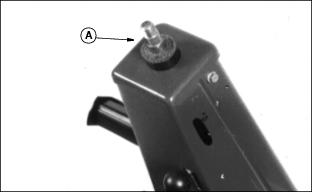
2. Install foam washer (A) on shaft.
3. Install steering wheel on shaft.
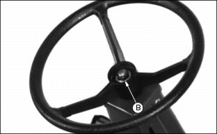
4. Install and tighten nut (B) 13-16 N·m (10-12 lb-ft).
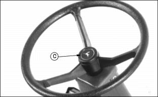
5. Put O-ring on steering wheel cap (C). Apply a light coat of John Deere multipurpose grease or an equivalent on O-ring.
7. Remove backing from decal. Apply decal to cap.
Installing Seat
2. Fasten seat to base with four 5/16 x 5/8 inch bolts (A).
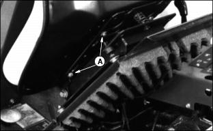
Install ROPS
NOTE: If Front Mower is to be used for low-clearance operation, and ROPS is not installed, remove seat belt from the seat base.
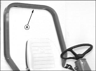
1. Install ROPS (A) angle toward rear of tractor.

2. Put four flange head cap screws (B) through holes in ROPS.
3. Install spacers (C) and lock nuts (D) (bolt head to the front and spacers to the rear).
4. Tighten bolts to 136 N·m (100 lb-ft).
Checking Tire Pressure
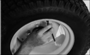
2. Check tire pressure with an accurate gauge.
Checking Tire Pressure (Continued)
NOTE: ALL REAR TIRES = 16 x 6.50 - 8, TIRE PRESSURE = 190 (28)
Install Front Wheels
NOTE: Save six wheel bolts used to attach axle to shipping stand.
Use these bolts and other four wheel bolts in bag of parts to install front wheels.

2. Install and tighten wheel bolts to 81-95 N·m (60-70 lb-ft).
3. Inform customer to tighten bolts again after 3 and 10 hours of use. (See Service Interval Chart)