![]()
M653, M655 and M665 PIN (010001- )
Introduction
Safety Signs
Controls
Operating Machine
Replacement Parts
Service Machine Safely
Service Interval Chart
Service Lubrication
Service Engine
Service Transmission
Hydrostatic Transmission and Hydraulic Oil
Cleaning Hydraulic Oil Cooler Fins
Check Hydrostatic Transmission Oil Level
Change Hydrostatic Transmission Oil and Filter
Checking and Replacing Pump Drive Belt
Check and Adjust Reverse Spring Detent
Checking and Adjusting Motion Control Linkages
Service Steering & Brakes
Service Mower
Service Electrical
Service Miscellaneous
Troubleshooting
Storing Machine
Assembly
Specifications
Warranty
John Deere Service Literature
John Deere Quality Statement
Copyright© Deere & Company

Service Transmission
Hydrostatic Transmission and Hydraulic Oil
Use the following oil viscosity based on the air temperature range. Operating outside of the recommended oil air temperature range may cause premature hydrostatic transmission failure.
The following oil is REQUIRED:
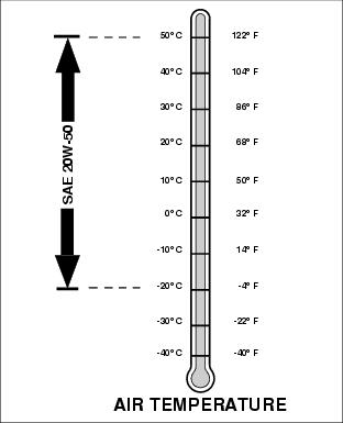
· API Service Classification SG or higher
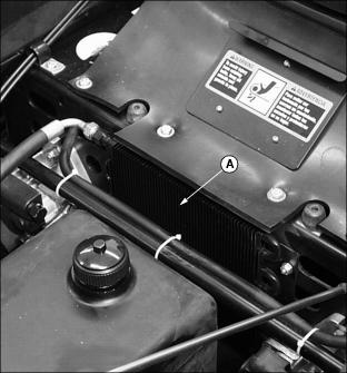
Cleaning Hydraulic Oil Cooler Fins
IMPORTANT: Avoid damage! To ensure proper cooling, keep the hydraulic oil cooling fins clean at all times. Operating the machine with obstructed cooling fins could cause damage due to overheating. |
1. Stop engine and engage park brake.
2. Lift and secure operator seat in the raised position.
3. Locate hydraulic oil cooler behind the hydraulic oil reservoir tank.
4. Clean hydraulic oil cooler fins (A) with a rag, brush, or compressed air.
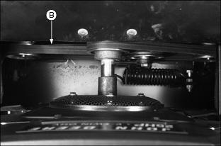
Check Hydrostatic Transmission Oil Level
IMPORTANT: Avoid damage! Check oil level in reservoir tank when oil is cold. DO NOT overfill oil reservoir tank. Oil will expand during operation and could overflow. |
1. Park machine on a level surface.
2. Stop engine and engage the park brake.
3. Lift and secure operator seat in the raised position.
4. Thoroughly clean area around reservoir fill cap.
5. Remove cap (A) from the oil reservoir tank filler neck. Visually check level of fluid.
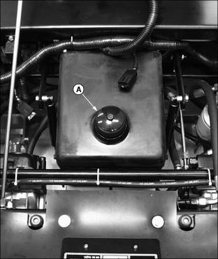
· Fluid level should be 44-51 mm (1-3/4-2 in.) below the top of the tank filler neck.
6. Add oil, if necessary. (See Hydrostatic Transmission and Hydraulic Oil in this section for the correct application.)
7. Install cap on filler neck.
Change Hydrostatic Transmission Oil and Filter
1. Park machine on a level surface.
2. Stop engine and engage the park brake. Allow engine and hydraulic oil reservoir to cool.
3. Lift and secure operator seat in the raised position.
4. Turn transmission oil filter (A) counterclockwise to remove.
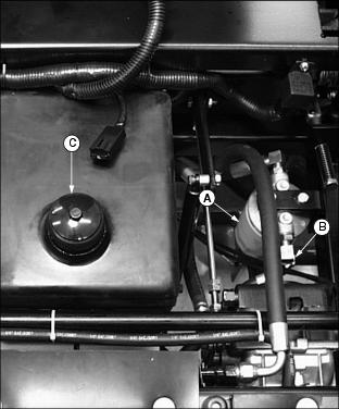
5. Remove hydraulic "INLET" hose (B) from rear filter fitting and allow transmission oil to drain into a drain pan with at least a 7.6 L (2.0 gal) capacity.
6. Apply a film of clean oil on gasket of new filter.
7. Install filter. Turn filter clockwise until gasket makes contact with the mounting surface. Tighten 1/2 to 3/4 turn after gasket contact.
8. Install and tighten hydraulic "INLET" hose (B).
9. Clean area around reservoir fill cap.
10. Remove cap (C) from the oil reservoir tank filler neck.
11. Fill oil reservoir with approximately 7.6 L (2.0 gal) of oil. (See Hydrostatic Transmission and Hydraulic Oil in this section for the correct application.)
13. Move throttle lever to the FAST (r) position.
15. Cycle motion control levers forward and rearward several times. Check for leaks around filter.
16. Stop the engine. Check oil level. Add oil as necessary. (See Checking Hydraulic Oil Level in this section.)
Checking and Replacing Pump Drive Belt
NOTE: The transmission drive belt will not require a tension adjustment. Belt is self-adjusted using a spring tensioner.
Checking Belt:
1. Stop engine and engage the park brake.
2. Lift and secure operator seat in the raised position.
3. Open rubber access door (A).
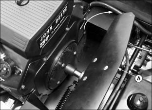
4. Inspect belt (B) for excessive wear, damage or stretching while in position on the transmission sheaves and drive belt tensioner pulley.
Replacing Belt
1. Remove belt from drive sheaves and idler pulley.
· To make removal and installation of the belt easier, carefully move spring loaded idler (C) to the LEFT using a pry bar or large screwdriver in location (D).

2. Install belt onto drive sheaves and idler pulley as shown.

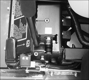
Check and Adjust Reverse Spring Detent
Check Adjustment
1. Park machine on a hard, level surface.
2. Stop engine and engage park brake.
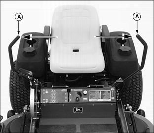
3. Pull both motion control levers (A) completely rearward to the REVERSE position and release to the NEUTRAL position.
4. Check where each motion control lever is relative to the NEUTRAL position slot in the operator station console.
· If the motion control levers (A) are not centered in the neutral slot and do not have the ability to pivot outward into the NEUTRAL LOCK position (B), an adjustment is necessary.
Picture Note: The top photo shows the motion control lever centered in the neutral slot in the NEUTRAL position.

Picture Note: The bottom photo shows the motion control lever pivoted outward into the NEUTRAL LOCK position.
Reverse Spring Detent Adjustment:
1. Adjust operator seat rearward as far as possible.
2. Lift and secure operator seat in the raised position.
3. Remove support rod (C) from side of seat frame.
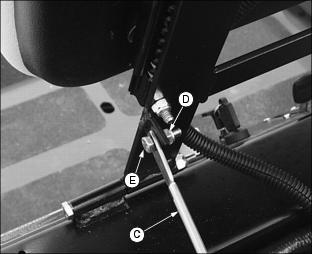
· Remove lock nut (D) and hex screw (E).
4. Tilt seat forward to rest on front frame.
NOTE: Right and left motion control levers can be adjusted independently.
5. Move the right motion control lever (A) to the NEUTRAL position.
6. Pull the motion control lever rearward until the clevis pin (F) on the arm below the pivot shaft (G) comes in contact with the rear of the slot (H).
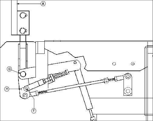
· Slight spring pressure should be felt.
7. Loosen hex nut (I) from the yoke (J).
8. Make sure clevis pin (F) makes contact with the rear of slot (H).
9. Apply slight rearward pressure to the right motion control lever (A). Turn the head of the adjustment bolt (K) clockwise or counterclockwise until the lever is centered in the neutral slot.
10. Tighten hex nut (I) against the yoke (J).
11. Repeat procedure for the left motion control lever.
NOTE: When properly adjusted the motion control levers will return to the NEUTRAL position from the REVERSE position and REVERSE motion will stop if the motion control levers are released.
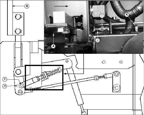
Checking and Adjusting Motion Control Linkages
· If it is necessary to run an engine in an enclosed area, use an exhaust pipe extension to remove the fumes. |
Check Adjustment
NOTE: Check and adjust motion control linkages with the machine parked on a hard, level surface.
2. Set throttle lever to the 1/2 fast position.
4. If the rear drive wheels begin to creep, an adjustment is required.
Adjust Linkages
NOTE: The reverse spring detent adjustment must be completed before the motion control linkages can be adjusted.
1. Stop engine and engage park brake.
2. Adjust operator seat rearward as far as possible.
3. Move both motion control levers (A) to the NEUTRAL LOCK position.
4. Lift and secure operator seat in the raised position.
5. Remove support rod (B) from side of seat frame.

· Remove lock nut (C) and hex screw (D).
NOTE: The operator seat must be adjusted completely to the rear to allow access to the console controls.
6. Tilt seat forward to rest on front frame.
7. Raise rear of machine with a safe lifting device.
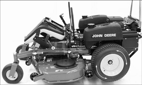
· Support with wood blocks or jackstands.
· Rear drive wheels must have the ability to rotate freely.
8. Activate operator seat safety switch.
NOTE: To prevent damage to the bottom of the operator seat, cover end of wood block with a rag.
· Place a wood block (E) approximately 25-30 cm (10-12 in.) long between the foot plate and the center of the seat as shown.
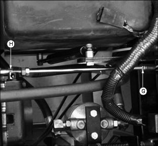
9. Locate left and right motion control linkages (F).
· Linkage rods connect each pump to motion control assemblies.

Picture Note: Lower photo to the right shows a close-up view of the RIGHT motion control linkage.
NOTE: Hex nut (G) on each linkage rod has left hand threads.
10. Loosen hex nut (G) and hex nut (H) behind each ball joint (I).
12. Set throttle lever to the 1/2 fast position.
NOTE: Right and left motion control levers can be adjusted independently.
14. Move the RIGHT motion control lever into the NEUTRAL position.
15. Adjust the RIGHT motion control linkage.
· Rotate the double hex nuts (J) on the rod in either direction until the creep is gone.
16. Move the RIGHT motion control lever completely forward in the slot and then back to the NEUTRAL position in the slot.
· The drive wheel must stop completely.
17. Move the RIGHT motion control lever completely rearward in the slot.
NOTE: If the lever fails to return to the NEUTRAL position in the slot and the drive wheel continues to creep, a reverse spring detent adjustment may be necessary.
· Lever should return back to the NEUTRAL position in the slot.
· The drive wheel must stop completely.
· Run engine at full throttle to make sure both drive wheels do not creep.
· Repeat steps 14-18 if further adjustment is required.
20. Repeat procedure to adjust the LEFT motion control linkage.
21. Tighten hex nut (G) and hex nut (H) against each rod ball joint.
23. Move both motion control levers to the NEUTRAL LOCK position.
24. Remove wood block from between foot plate and the operator seat.