M653, M655 and M665 PIN (010001- )
Introduction
Safety Signs
Controls
Operating Machine
Replacement Parts
Service Machine Safely
Service Interval Chart
Service Lubrication
Service Engine
Service Transmission
Service Steering & Brakes
Service Mower
Service Electrical
Service Miscellaneous
Troubleshooting
Storing Machine
Assembly
Check Machine Safety Interlock System
Specifications
Warranty
John Deere Service Literature
John Deere Quality Statement
CopyrightŠ Deere & Company

Assembly
Prepare for Assembly
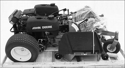
ˇ Remove front mower from the shipping crate.
ˇ Cut plastic tie straps fastening the rear drive wheels to the shipping crate.
ˇ Cut plastic tie straps fastening the front and rear of the front mower to the shipping crate pedestal.
ˇ Cut plastic tie strap fastening the grass discharge chute in the raised position.
Install Rear Drive Wheels
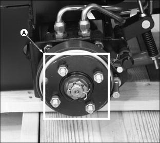
1. Remove four wheel nuts (A) stored on each rear drive wheel hub.
2. Lift rear of machine with a safe lifting device.
3. Check drive wheel tire inflation pressures:
ˇ Keep tires inflated to 69-97 kPa (10-14 psi).
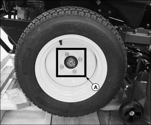
4. Attach one wheel to each hub using four wheel nuts (A), tighten until snug.
ˇ Mount each wheel with the valve stem facing to the outside.
5. Lift front of machine with a safe lifting device
6. Remove shipping crate base from under machine.
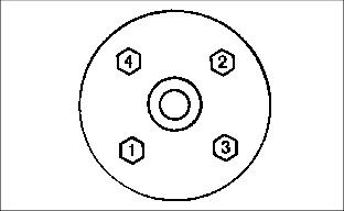
ˇ Tighten wheel nuts in numbered sequence shown for safe wheel installation. Tighten alternately until recommended torque value is reached.
ˇ Tighten bolts to 100 Nˇm (75 lb-ft.).
Install Motion Control Levers
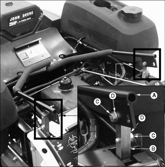
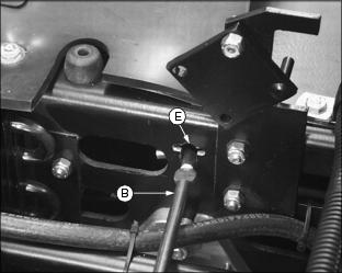
1. Remove motion control levers (A) from the left and right control arms (B).
ˇ Remove four 3/8" x 1" hex cap screws (C) and four 3/8" spring washers (D) attaching the control levers to the control arms.
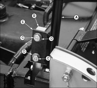
2. Install each motion control lever (A) to the outside of the control arm (B) with two 3/8" x 1" hex cap screws (C) and two 3/8" spring washers (D).
ˇ Motion control lever tabs (E) should be directed to the rear of the mower.
ˇ Position each motion control lever so the attaching hardware is installed in the center of the slotted tab holes.
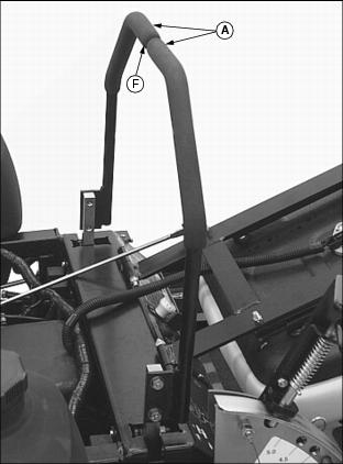
3. Check motion control lever (A) alignment.
ˇ Move both motion control levers to the NEUTRAL position.
ˇ Check gap (F) between the levers. The recommended gap is 3-6 mm (1/8-1/4 in.).
ˇ Check levers for equal alignment.
ˇ If positions of the levers are unequal, loosen attaching hardware and slide both levers forward or rearward to desired position within tab slots until levers are aligned.
NOTE: If the ends of the levers strike against each other while in the NEUTRAL position, move the levers outward to the NEUTRAL LOCK position and carefully bend them outward. Move them back to the NEUTRAL position and check for the recommended gap of 3-6 mm (1/8-1/4 in.).
Install Seat Support Rod
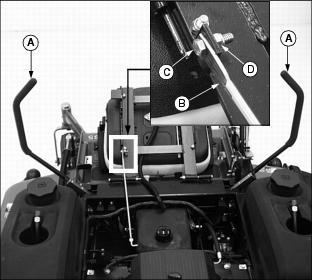
1. Move the motion control levers (A) to the swing-out neutral lock position.
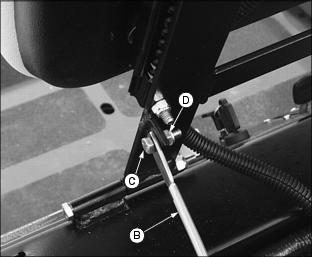
2. Remove seat support rod (B) attached to the bottom of the seat mount frame.
ˇ Remove 5/16" x 1" hex screw (C) and 5/16" lock nut (D).
3. Install "L" shaped end of support rod (B) into slotted frame hole (E).
ˇ The "L" shaped end of the support rod must be positioned to the right as shown.
4. Attach support rod (B) to the outside of the seat frame mounting tab with a 5/16" x 1" hex screw (C) and a 5/16" lock nut (D). DO NOT overtighten, rod must pivot freely.
5. Raise support rod slightly. Lower operator seat.
Check Tire Pressure
2. Check tire pressure with an accurate gauge.
Check Engine Oil Level
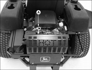
1. Remove oil dipstick (A). Wipe it clean.
3. Remove dipstick and check oil level. Oil level must be between ADD and FULL marks on dipstick.
Check Mower Deck Level
The mower deck is assembled and adjusted at the factory. After machine is completely assembled check the mower deck level.
Check the "Front to Rear" and "Side to Side" level. Refer to the Operating Mower section for instruction on how to check and adjust mower deck level.
Check Machine Safety Interlock System
Perform safety system check to make sure the electronic safety interlock circuit is functioning properly. See Testing the Safety Interlock System in the Operating section.
Break-In Electric PTO Clutch
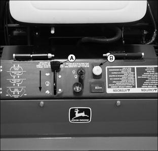
1. Start engine and push throttle lever (A) down to the full throttle (r) position.
2. With no load on mower, ENGAGE PTO switch knob (B) and allow mower to run for 10 seconds.
ˇ DISENGAGE PTO switch knob and wait 10 seconds.
3. Repeat Step 2 twelve to fifteen times to properly burnish PTO clutch.

