![]()
Introduction
Safety Labels
Controls
Operating - Machine
Operating - Cutting Units
Service Safely
Service Interval Chart
Service Lubrication
Service Engine
Service - Cutting Units
Removing And Installing Bed Knife
Removing Rotary Brush Or GTC (Greens Tender Conditioner)
Removing And Replacing Reel Without GTC (Greens Tender Conditioner)
Removing And Replacing Reel With GTC (Greens Tender Conditioner)
Adjusting Reel Or Roller Drive Chains
Checking Tire Pressure (Transport Wheels)
Service - Belts
Troubleshooting
Storing Machine
Assembly
Specifications
Warranty
John Deere Quality Statement
Copyright© Deere & Company

Service - Cutting Units
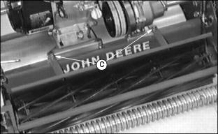
Backlapping
IMPORTANT: Avoid damage! Backlap cutting reel routinely to prolong life of reel. Do not overtighten bed knife or excessive wear at the ends will occur. |
To maintain sharp edges required on cutting reel, follow this procedure:
1. Before backlapping, adjust bed knife to cutting reel (See Adjusting Bed Knife To Reel in this section). The bed knife must be adjusted to assure a light, even contact over the entire length of the blade.

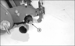
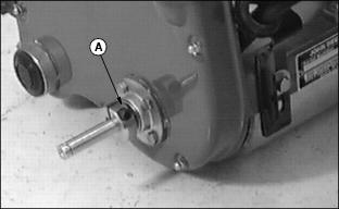
3. Screw 3/8-in. backlapping bolt
into reel shaft.
4. Put socket head extension (B)
on bolt.
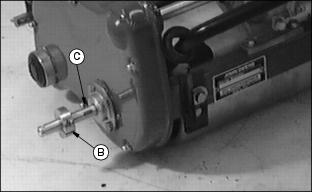
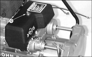
5. Connect the extension to the backlapping unit (C).
· DISENGAGE the GTC (Greens Tender Conditioner) before backlapping. |
6. Turn on the backlapping motor. Make sure the reel is running in reverse.
7. Using a long handled brush, apply a reel sharpening compound from one end of the reel to the other as uniformly as possible. Repeat application in opposite direction. Continue to turn reel backwards until reel is quiet (approximately 3 minutes).
8. Periodically visually check blade appearance. Continue to backlap until blades are evenly sharpened.
9. Turn off motor, and disconnect backlapping unit.
10. Thoroughly wash off all reel sharpening compound with water.
11. Remove backlapping bolt and install cover.
12. Readjust bed knife to reel. (See Adjusting Bed Knife To Reel in this section.)
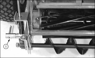
Removing And Installing
Bed Knife
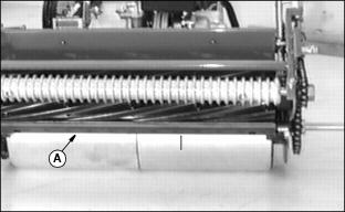
1. Remove (13) screws and bed
knife (A).
2. Install bed knife and new screws. Alternate tightening by starting with center screw.
3. Adjust bed knife to reel, this section.
4. Backlap cutting reel, this section.
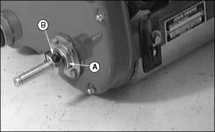
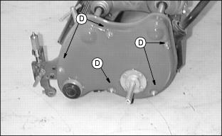
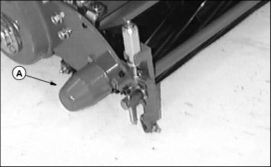
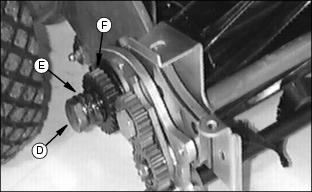
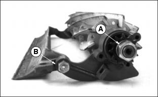
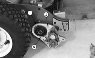
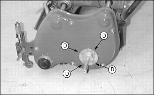
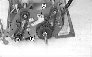
Removing Rotary Brush Or GTC (Greens Tender Conditioner)
NOTE: The following hardware when removed needs to be saved for future use:
· Small gear, and key, Step 3.
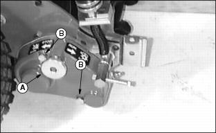
1. Turn knob (A) full COUNTERCLOCKWISE past detent position.
2. Remove two bolts (B) and washers, and gear case cover.

3. Remove nut (C), small gear (D), and key.
4. Remove nut (E) and spacer (F).
5. Remove bracket (I) by removing
T-handle (J), lock washer, and bolt.
6. Remove rotary brush or GTC (greens tender conditioner).
7. Install bolt back through the adjusting knob eyebolt , lock washer, and T-handle for storage.
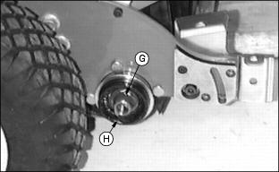
9. Install special cap screw (found in the bag of parts) into gear case bearings where nut (C) and gear (D) were removed. Hold in place with nut removed previously.
10. Install gear case cover and tighten bolts.
11. Reverse above steps to install.
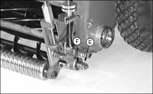
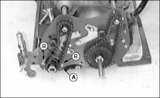
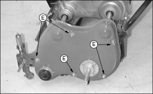
Removing And Replacing
Reel
1. Remove transport wheels, if your machine is equipped with them.
2. Loosen hex socket screw (A) and remove collar (B) and key.
4. Remove five acorn nuts (D) (10 mm), washers, and shoulder bolts on left drive cover.
5. Loosen bolt (E) to release tension and remove reel drive chain (F).
6. Loosen two cap screws and lift
out shield (C).
Removing And Replacing Reel Without GTC
(Greens Tender Conditioner)
2. Remove shoulder bolt (B) , spring, spacer, and collar.

3. Loosen clamp screw (C) (on each side) and remove bed knife adjusting handles (D).
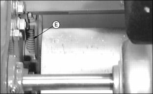
4. Remove spring (E) and T-bolts (one each side).
5. Rotate bed knife support downward.
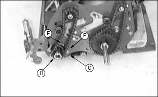
6. Remove three bolts (F) and shield (G) from left bearing housing. Left end of reel (H) will lower.
7. Remove three bolts from right bearing housing.
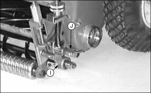
Removing And Replacing Reel
With GTC (Greens Tender
Conditioner)
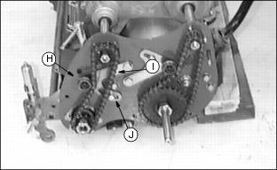
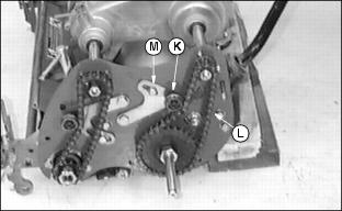
1. Turn knob (A) COUNTERCLOCKWISE past detent position.
2. Remove two bolts and washers (B) and remove gear case cover (C).
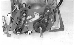
3. Remove shoulder bolt (D), spring (E), and gear (F).
4. Remove key (G) and collar (H).
5. Remove adjuster T-handle (I), lock. washer, and bolt from both sides.
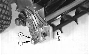
6. Remove nut (J), gear (K), and key.
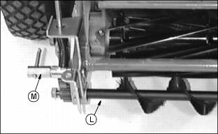
7. Remove vertical cutter (L), or rotary brush.
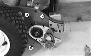
8. Remove snap ring (M), gear case (N), and collar (O).
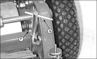
9. Loosen clamp screw (P) (on each side) and remove bed knife adjusting handles (Q).
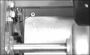
10. Remove spring (R) and T-bolt (one each side).
11. Rotate bed knife support downward.
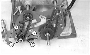
12. Remove three bolts (S) and shield (T) from left bearing housing. Left end of reel (U) will lower.
13. Remove three bolts from right bearing housing.
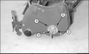
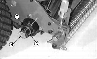
Inspecting Bearing
1. Inspect bearing for roughness and ease in rotating.
2. Remove nut (A), washer, sprocket, key, and snap ring.
3. Remove shoulder bolt (B) and bearing frame.
4. Remove and replace bearing and
seal. If one bearing is being replaced,
replace both at same time.
Install Reel Assembly
1. Install reel assembly and shield (A) using three cap screws (B).
2. Repeat on opposite side using three cap screws.

3. Install spring (C) and T-bolt (one on each side)
4. Install adjusting handles (D). Use adjusting handles to move bed knife to just clear reel.
5. Tighten clamp screws (E) (one on each side).
6. Without Rotary Brush: Install collar, spacer (F), spring (G), and shoulder bolt (H).
· With Rotary Brush: Install collar (I), gear case (J), and snap ring (K).
· Install vertical cutter or rotary brush (L).
· Install bolt, lock washer, and adjuster T-handle (M) on both side.

· Install key and gear (N), and
nut (O).
· Pry end of reel to left side to check for end play. Reel must slide easily.
· Lubricate both sides of reel.
· Install cap or gear case cover.
· Adjust reel drive chain. (See Adjusting Reel Or Roller Drive Chains in this section.)
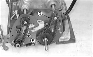
· Lubricate drive chains (P) and (Q) using John Deere EP Moly Grease or equivalent.
· Reverse disassembly on left-hand side.
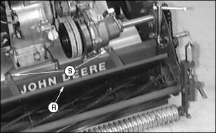
· Slide shield (R) under cap screws and washers (S).
NOTE: Make sure there are two washers between the engine support and the shield bracket.
· Check to make certain three tabs on shield are attached to bed knife shoe.
· Backlap reel. (See Backlapping Reel in this section.)
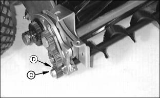
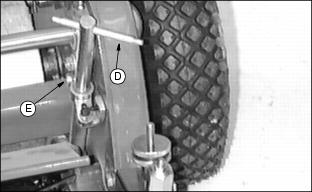
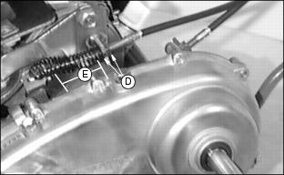
Adjusting Reel Or Roller Drive Chains
1. Remove transport wheels, if equipped.
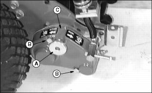
2. Loosen hex socket screw (A).
3. Remove collar (B) and key (C).
4. Loosen four bolts (D) (13 mm).
5. Remove five acorn nuts (E) (10 mm), washers and shoulder bolts on left drive cover.
7. Loosen bolt (F) (reel drive chain) or bolt (G) (roller drive chain).
8. Reel Drive Chain: Pivot idler bracket (H) up or down until chain deflects 6 mm (1/4-in.) at mid span (I) opposite idler.
10. Roller Drive Chain: Pivot idler bracket (K) up or down until chain deflects 11 mm (7/16-in.) at mid span (L) opposite idler.
11. Lubricate drive chains using John Deere EP Moly Grease or equivalent.
13. Reverse disassembly steps.
Adjusting Brake
NOTE: Make sure reel clutch is DISENGAGED.
1. With engine OFF, travel clutch in neutral, and brake ENGAGED; pull mower rearward.
2. If drive roller or transport tires drag, brake is properly adjusted.
3. If drive roller or transport tires turn, do the following:
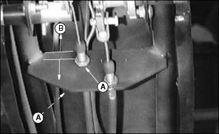
· Loosen jam nuts (A) holding cable in handlebar.
· If more adjustment is needed do the following:
· Remove cover by loosening bolt (C) (16 mm).
· Loosen jam nuts (D) holding brake cable near the brake:
· If still not properly adjusted,
Repeat Step 3.
· Install cover and tighten bolt.
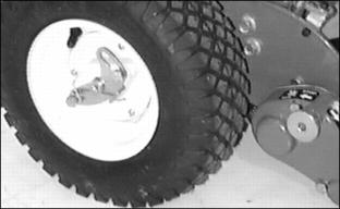
Checking Tire Pressure (Transport Wheels)
Check tire pressure of the transport wheels, if your machine is equipped with them.