![]()
Introduction
Safety Labels
Controls
Operating - Machine
Operating - Cutting Units
Service Safely
Service Interval Chart
Service Lubrication
Service Engine
Service - Cutting Units
Service - Belts
Troubleshooting
Storing Machine
Assembly
Install Brake And Travel Clutch Cables
Installing Rotary Brush Or GTC (Greens Tender Conditioner)
Specifications
Warranty
John Deere Quality Statement
Copyright© Deere & Company

Assembly
Identify Parts
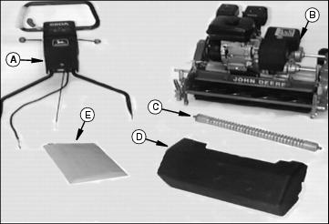
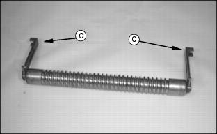
Attach Handlebar
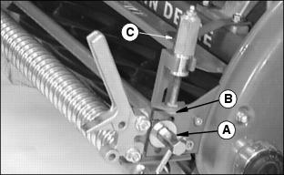
1. Remove bracket (A) by removing bolt and washer (one on each side).
2. Insert handlebar (B) in brackets.
3. Slide end of handlebar over pegs (C).
4. Install brackets to mower using bolts and washers removed above.
5. Adjust handlebar. (See Adjusting Handlebar in Operating The Cutting Unit section.)
NOTE: Make sure brackets are straight UP and DOWN, and not at an angle.
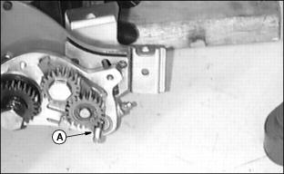
Install Brake And Travel
Clutch Cables
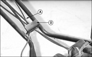
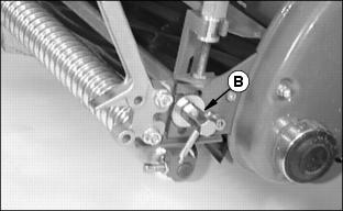
1. Route cables (A) through slotted hole in lower handlebar bracket (B).
NOTE: Slide caps (C) up and remove top nut (D) in order to get cables into slots. Make sure one nut is on either side of bracket before tightening.
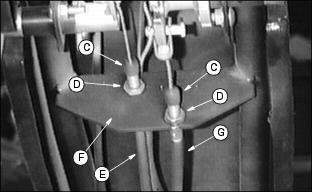
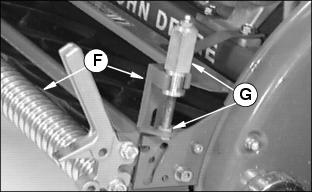
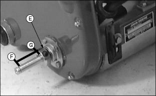
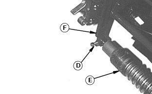
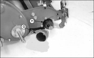
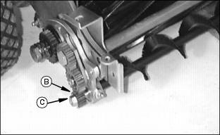
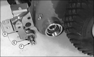
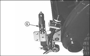
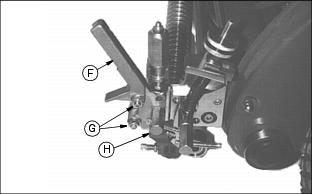
2. Put brake cable (E) into upper slot in handlebar bracket (F) and clutch cable (G) into lower slot.
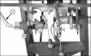
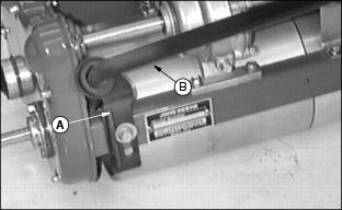
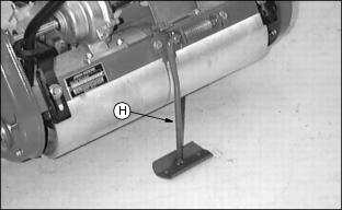
3. Remove carriage bolt (H) and rotate brake lever (I) to put end of cable (J) in hole in brake arm lever.
NOTE: Cable end MUST swivel FREELY. (See Adjusting Brake in the Service-Cutting Unit section.)
4. Install carriage bolt and nut and tighten
5. Apply some grease to the cable end.
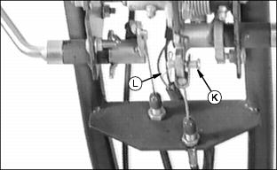
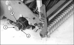
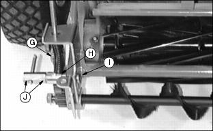
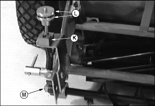
6. Fasten end of travel clutch cable
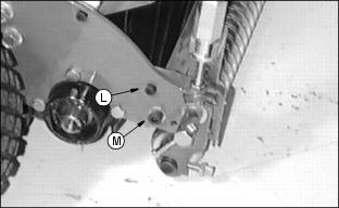
to hole in travel clutch bracket with drilled pin (K) and cotter pin (L).
7. If necessary, adjust cables. (See Service-Cutting Unit, Adjusting Brake and Adjusting Drive Belts in that section.)
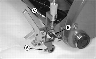
Install Throttle Cable
1. On handlebar console, move throttle lever to the r SLOW position.
2. Remove air cleaner assembly.
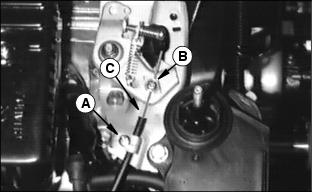
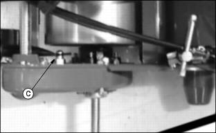
3. On carburetor linkage, loosen screws (A and B).
4. Put throttle cable (C) under bracket and screw (A) and through swivel and screw (B).
6. On handlebar console, move throttle lever from the t SLOW position to the r FAST position.
7. Observe carburetor linkage, linkage must travel from slow idle
stop to full throttle.
8. If necessary, loosen both screws, reposition throttle cable and tighten screws.
9. Repeat steps 6 - 8 until carburetor linkage has full travel between the slow idle stop to full throttle.
10. Install air cleaner assembly.
Install Run\Off Switch Cable
1. Route run\off switch wiring harness:
· Route wiring harness (A) over recoil starter.
· Bend tabs (B) to hold harness.
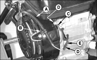
· Attach run\off switch ground wire (C) with bolt (D).
· Put male end of connector (D) into female end of connector (E).
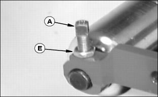
Install Front Roller
NOTE: Installation of Grooved Roller and Smooth Roller is the same. The Grooved Roller is shown.
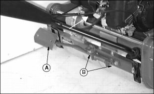
1. Loosen jam nut and remove set bolt (A). (Repeat on the other side.)
2. Remove T-handle (B), lock washers, washer and bolt.
4. Position brackets (C) onto roller.
NOTE: Do not put set bolts into holes in roller shafts.
5. Tighten set bolt (A) to hold bracket onto roller shaft.
7. Install roller assembly (F). If necessary, remove adjusting bolt (G) to fit the roller assembly.
8. Install T-handle (B), lock washers, washer and bolt.
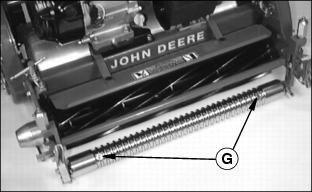
9. Lubricate roller at points (G).
NOTE: DO NOT over-lubricate. Excess grease could fall from the mower during operation.
10. Adjust cutting height. (See Adjusting Cutting Height in Operating The Cutting Unit section.)
Installing Grass Catcher
NOTE: Install width indicator on Model 180A to help line up mower with cutting area. Bag of parts is included in operator manual packaging.
1. Place width indicator bracket (A) in recessed groove (D) on top of grass catcher.
2. Using the bracket hole as a guide, drill 7mm hole in catcher.
3. For each side, install M6 x 16 cap screw (B), washer and locknut (C).
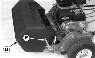
· Install grass catcher (D) onto brackets (E).
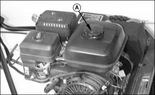
2. Remove fuel tank cap (A) and fill fuel tank.
· Fuel tank capacity: 2.5 L
(2.6 U.S. qt).
· Install fuel tank cap and tighten.
Engine Break-In
· If it is necessary to run an engine in an enclosed area, use an exhaust pipe extension to remove the fumes. |
Advise customer to follow this engine break-In procedure.
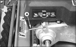
1. Reel Clutch handle (A) should be in the STOP position.
2. Allow engine to run and warm up for 15 minutes at 1/2-3/4 throttle before applying load.
3. After first 20 hours, change engine oil while engine is warm.
Install Transport Wheels
The following should be in the bag of parts:
1. Attach stand (A) to frame of mower using two bolts (B).
3. Slide drive collar (D) (flat side of collar facing machine).
4. Set distance from inside groove (F) on end of shaft to end (G) of drive collar at 62 mm (2.4-in.).
6. Repeat Steps 2, 3, 4, and 5 for the other side.
NOTE: Before removing or installing wheels, DISENGAGE travel clutch and STOP engine.
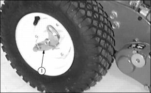
8. Slide transport wheel on shaft and rotate wheel to engage collar.
9. Engage plate (I) in groove of shaft. Repeat for the other side.
11. Check for 125-140 kPa (18-20 psi) tire pressure.
Installing Rotary Brush Or GTC (Greens Tender Conditioner)
The following parts should be in the bag of parts:
NOTE: The following hardware, when removed, needs to be saved for future use:
· O-ring and reel cap in Step 5.
1. Remove T-handle (A), lock washers, washer, and bolt. Discard bolt.
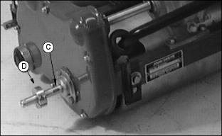
2. Remove nut (B) (bottom nut) and adjusting knob (C).
3. Loosen jam nut and set screw (D) (on both sides) and remove roller (E) and bracket (F).
4. Repeat the above steps for the other side.
5. Remove reel cap (G) and O-ring (H).
6. Remove reel bolt (I), spring (J), and spacer (K).
7. Remove one M6 x 16 socket head cap screw (L) and one M8 x 25 socket head cap screw (M) and lock washer. Discard lock washer.
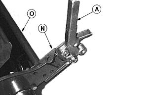
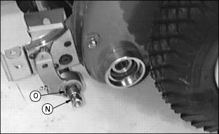
9. Remove catcher brackets (A) from each side. Discard bolts. Remove front brace (N) and bracket (O) from each side.
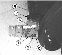
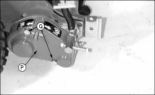
10. Install bracket (P), pad (Q), and front brace (R), and fasten with four socket head screws (S) and (T):
· Two that were removed earlier
(S) and two out of the bag of parts (T).
· Two nuts out of bag of parts for socket head screws (T).
11. Repeat for the other side.
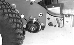
12. Install collar (U) with flange away from mower frame.
NOTE: If necessary, tap collar fully onto the casting housing using a hammer and punch.
NOTE: Gear case comes assembled in the bag of parts.
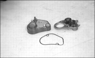
14. Loosen two bolts on gear case cover and remove gear case and gasket.
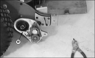
15. Slide gear case onto hub and fasten with snap ring (W).
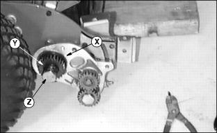
17. Grease spring (Y) and fasten with bolt (Z).
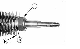
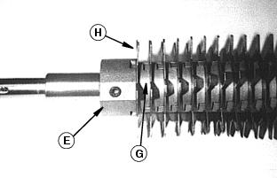
NOTE: 180A models (GTC) only-Remove hex nut (F). Remove all spacers (G) and blades (H).
10 blades total are being removed, leaving 65.
Re-install 5 spacers (G) without blades (H) and slide down shaft to collar (E). Install blade then spacer until only six spacers remain. Install remaining 6 spacers (without blades) and hex nut. Tighten nut (F) enough to remove all play between spacers and blades. DO NOT over-tighten.
18. Install rotary brush or GTC (greens tender conditioner) shaft (A) through bearing.
19. Install key and gear (B), and lock nut (C). (Do not tighten at this time.)
20. Install rotary brush or GTC (green tender conditioner) shaft through bearing in bracket (D) on left side.
21. Install spacer (E) and lock nut (F) on shaft. (Do not tighten at this time.)
22. Put spring (G) on adjusting knob eyebolt (H).
23. Put washer on top of spring.
Slide assembly through bracket.
24. Fasten with M8 x 70 carriage
bolt (I), (2) lock washers, and T-handle (J).
25. Repeat Steps 19 and 20 on the other side.
26. Put step block (K) on top of adjusting eyebolt.
27. Screw on jam knob and locking knob (L).
29. Tighten lock nut (M) on gear
case side.
30. Tighten lock nut (N), then loosen 1/4 turn. Spacer (O) must turn easily.
31. Lubricate reel bearing until grease comes out around gears. (See Service-Lubrication section.)
33. Put a thin layer of grease on gasket and install gasket, and cover (P) over gear case.
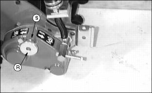
35. Install knob (R) on gear shaft and fasten with set screw (S) and tighten.
36. Install front roller that was removed in steps 1-4.
37. Install HOC (Height Of Cut) brackets (E), adjustment knobs, and front roller. Do not tighten set screws in HOC bracket.
38. Install catcher brackets (F). Mount brackets using front hole (G) on bracket. Use (2) bolts (M8x30) supplied with kit.
39. Install new longer bolts (M8x40), flat washer, lock washer and T-handle (H).