![]()
Introduction
Safety Labels
Controls
Operating - Machine
Operating - Cutting Units
Service Safely
Service Interval Chart
Service Lubrication
Service Engine
Service - Cutting Units
Service - Belts
Adjusting Operator Presence Bail
Troubleshooting
Storing Machine
Assembly
Specifications
Warranty
John Deere Quality Statement
Copyright© Deere & Company

Service - Belts
Removing Drive Belts
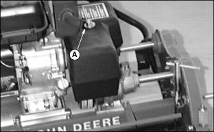
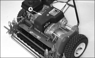
1. Remove bolt (A) (16 mm) and cover.
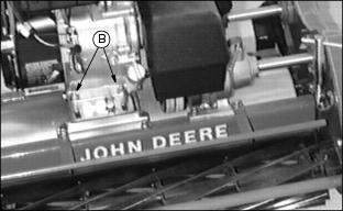
2. Remove two nuts (B) (13 mm) and bolts (on front of engine).
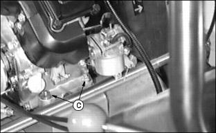
3. Remove two nuts (C) (13 mm) and bolts (on back of engine).
Installing Belts
1. Place belts on engine sheave.
2. Put engine on support with belts installed on gear case sheave.
3. Fasten with nut and bolts removed earlier. Do not tighten at this time.
4. Move engine rearward to tension belts. Engine sheave must be aligned with driven sheave.
5. Tighten four engine nuts (13 mm).
6. Check belt adjustment. (See Adjusting Drive Belts in this section.)
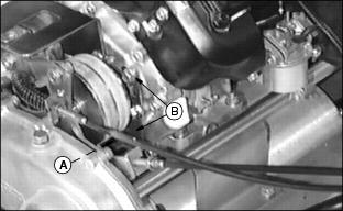
7. Adjust belt guide (A) using two bolts (B). There must be a clearance of approximately 1 mm (0.040-in.) between belt and guide when clutch is ENGAGED.
NOTE: Belt guide helps prevent movement when clutch is disengaged.
Adjusting Drive Belts
NOTE: With engine OFF and clutch in neutral, mower should roll freely.
When clutch is ENGAGED, main drive roller should not move. Excessive force should not be required to engage the clutch lever.
With engine running and clutch in neutral, mower should not move forward. Otherwise, additional adjustment of belt idler is required.
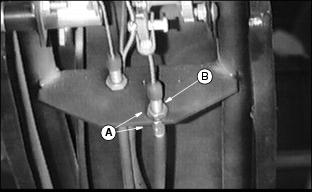
1. Loosen jam nuts (A) (one on each side of bracket).
2. Lengthen or shorten ferrule (B) to change belt idler tension.
NOTE: Set the belt idler tension just tight enough so that the main drive roller does not move when the clutch is engaged. Do not over-tighten the belt idler tension.
3. If more adjustment is needed, remove belt cover, and adjust cable at engine as done in Step 1.
· If additional adjustment is needed, loosen four engine bolts
(13 mm), and slide engine to tighten or loosen belts. Engine sheave and driven sheave must align.
· Tighten engine bolts. Repeat Steps 1 and 2.
Adjusting Belt Guide
1. Stop engine and wait for all moving parts to stop rotating.
3. Make sure drive belts are properly tensioned. (See Adjusting Drive Belts in this section.)
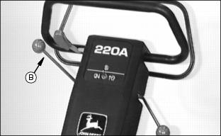
4. Move the clutch lever (B) forward to the ENGAGE position.
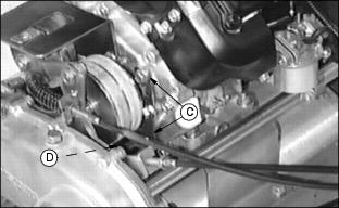
· Adjust belt guide (D) until there is a 1 mm (0.040-in.) clearance between drive belts and guide.
Adjusting Operator Presence Bail
NOTE: Cover removed for clarity of photo only.
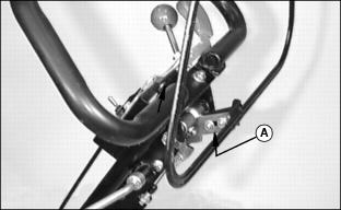
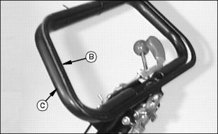
2. Position the bail (B) to the loop handlebar (C).
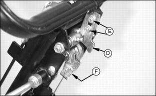
3. Rotate the engagement arm (D) upward as far as possible.
5. Check bail for proper operation. When bail is released, engagement arm (D) must fully engage clutch lever linkage (F).