![]()
Introduction
Product Identification
Safety
Operating
Replacement Parts
Service Intervals
Service Lubrication
Service Engine
Service Transmission
Change Hydraulic Oil and Filter
Checking and Replacing Pump Drive Belt
Checking and Adjusting Transmission Neutral
Adjusting Control Lever Neutral Start Switches
Service Steering & Brakes
Service Electrical
Service Miscellaneous
Troubleshooting
Storage
Assembly
Specifications
Warranty
John Deere Quality Statement
Service Record
Copyright© Deere & Company

Service Transmission
Hydraulic Oil
Use the following oil viscosity based on the air temperature range. Operating outside of the recommended oil air temperature range may cause premature hydrostatic transmission failure.
The following John Deere oil is preferred:
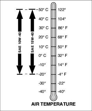
Other oils may be used if they meet the following:
· API Service Classification SJ
Check Hydraulic Oil Level
IMPORTANT: Avoid damage! Do not overfill oil reservoir tank. Oil will expand during operation and could overflow. |
NOTE: Check oil level in reservoir tank when oil is cold.
1. Park machine safely. (See Parking Safely in the Safety section.)
3. Clean area around reservoir dipstick cap (A).
4. Turn and remove dipstick cap from the oil reservoir tank.
6. Install dipstick cap but do not turn it.
8. Check oil level on dipstick.
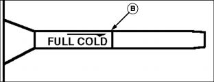
9. Oil should be to the top of the "FULL COLD" mark (B).
Change Hydraulic Oil and Filter
1. Park machine safely. (See Parking Safely in the Safety section.)
3. Allow engine and hydraulic oil reservoir to cool.
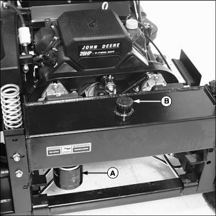
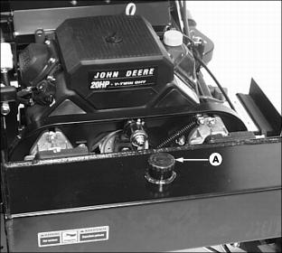
4. Turn hydraulic oil filter (A) counterclockwise to remove. Allow hydraulic oil to drain into a drain pan with at least a 5.7 L (1.5 gal) capacity.
5. Apply a film of clean oil on gasket of new filter.
6. Install filter. Turn filter clockwise until gasket makes contact with the mounting surface. Tighten 1/2 to 3/4 turn after gasket contact.
7. Clean area around reservoir dipstick cap.
8. Turn and remove dipstick cap (B) from the oil reservoir tank.
9. Fill oil reservoir with approximately 5.7 L (1.5 gal) of oil.
11. Move throttle lever to the fast position.
Remain alert to bystanders and the surroundings while operating the machine. |
13. Cycle control levers forward and rearward several times. Check for leaks around filter.
14. Stop the engine. Check oil level. Add oil as necessary.
Checking and Replacing Pump Drive Belt
Stop engine and wait for all moving parts to stop before servicing machine. |
NOTE: The transmission drive belt will not require a tension adjustment. Belt is self-adjusted using a spring tensioner.
Checking Belt:
1. Park machine safely. (See Parking Safely in the Safety section.)
3. Disconnect spark plug wires.
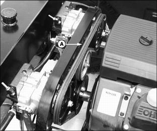
4. Inspect belt (A) for excessive wear, damage or stretching while in position on the transmission sheaves and drive belt tensioner pulley.
Replacing Belt
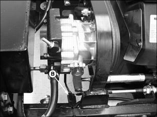
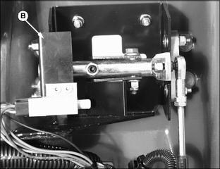
1. Disconnect PTO clutch electrical connection (B) located below the left steering pump.
NOTE: Do not remove the PTO driveshaft from the mower deck gearbox.This service procedure is easier when the driveshaft is removed from the clutch housing.
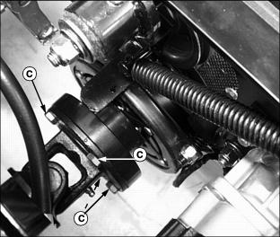
2. Disconnect mower deck PTO driveshaft by removing four hex bolts (C).
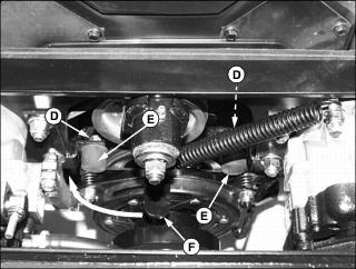
3. Remove lock nuts (D) and PTO clutch bumpers (E).
4. Stand on the right side of the front mower. Pull and hold spring loaded pump drive belt tensioner handle (F) rearward.
5. Remove belt from drive sheaves and idler pulley.
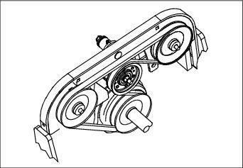
Picture Note: Belt installation as viewed from the rear of the machine.
· Pull and hold belt tensioner handle (F).
· Install belt onto drive sheaves and idler pulley as shown.
· Release belt tensioner handle.
7. Install PTO clutch bumpers.
8. Align PTO driveshaft mounting holes with the clutch mounting holes.
9. Install four hex bolts (C). Tighten alternately to 44 N·m (33 lb-ft).
10. Connect PTO clutch electrical connector.
Checking and Adjusting Transmission Neutral
· If it is necessary to run an engine in an enclosed area, use an exhaust pipe extension to remove the fumes. |
Check Adjustment:
1. Park machine on a hard, level surface.
3. Set throttle lever to the 1/2 fast position.
· If drive wheels begin to creep, an adjustment is required.
Transmission Neutral Adjustment:
3. Remove mower deck from the machine. (See Removing Mower Deck in the mower deck operator's manual.)
4. Elevate front of machine with a safe lifting device, wood blocks or jackstands.
· Drive wheels must have the ability to rotate freely.
· Drive wheels may be removed for better access to the transmission.
5. Move control levers to the swing-out neutral position.

7. Locate both steering control cables (A) under the front mower cowling.
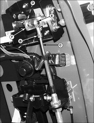
8. Disconnect left and right steering cable rod ends (C).
· Loosen and remove locknut (D).
· Remove eyebolt (E) from slotted arm plate (F).
9. Have a helper depress bottom of operator seat to activate the seat safety switch.
· If drive wheels continue to creep, a transmission drive pump dampener adjustment is required.
· If no drive wheel creep is detected, bypass the drive pump dampener adjustment and proceed to the control cable adjustment.
Adjust Transmission Drive Pump Dampeners:
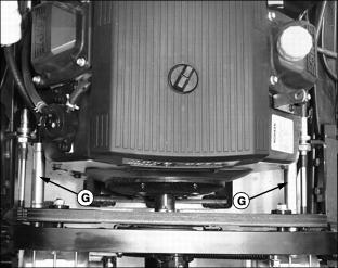
1. Locate left and right drive pump dampener assemblies (G).
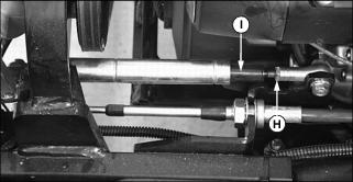
3. Rotate each dampener cylinder (I) until creep is gone.
5. Check adjustment. Continue to adjust dampeners until creep is gone.
Adjust Control Cables:

1. Loosen steering cable jam nuts (G).
NOTE: Eyebolts should be installed to the bottom of each slotted control arm plate.
2. Adjust cable rod ends (C) up or down until eyebolts (E) can be inserted absolutely perpendicular inside the slotted arm plates (F).
3. Install and tighten lock nuts (D).
5. Check adjustment. If further adjustment is required, repeat steps 1-4.
Adjusting Control Lever Neutral Start Switches
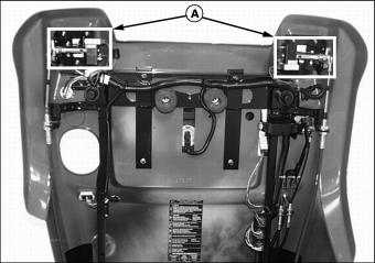
Both control lever neutral safety switch positions (A) are adjustable if necessary.
Test Neutral Start Switches
1. Park front mower on a hard, level surface.
5. Slowly move both control levers to a centered neutral position.
· If properly adjusted, the engine should stop.
· If the engine continues to run, a neutral start switch adjustment will be needed.