![]()
Introduction
Product Identification
Safety
Operating
Avoid Damage to Plastic and Painted Surfaces
Testing the Safety Interlock System
Testing Park Brake Safety Switch
Replacement Parts
Service Intervals
Service Lubrication
Service Engine
Service Transmission
Service Steering & Brakes
Service Electrical
Service Miscellaneous
Troubleshooting
Storage
Assembly
Specifications
Warranty
John Deere Quality Statement
Service Record
Copyright© Deere & Company

Operating
Daily Operating Checklist
o Remove grass and debris from machine.
o Clean engine oil cooling fins.
o Check area below machine for leaks.
Avoid Damage to Plastic and Painted Surfaces
· Do not wipe plastic parts unless rinsed first.
· Insect repellent spray may damage plastic and painted surfaces. Do not spray insect repellent near machine.
· Be careful not to spill fuel on machine. Fuel may damage surface. Wipe up spilled fuel immediately.
Operator Station Controls
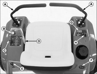
Miscellaneous Controls
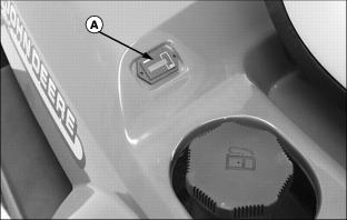
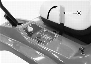
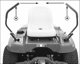
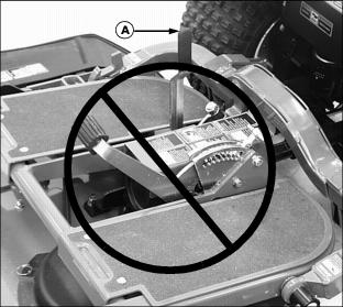
Adjusting Seat
1. Sit on the operator's seat.
2. Push and hold lever (A) to the left.
3. Slide seat forward or backward to desired position.
Testing the Safety Interlock System

NOTE: This unit is equipped with a electronic safety interlock. Engine will not start unless the PTO switch is in the disengaged position, the control levers are in the swing-out neutral position and the park brake lever is in thposition.
Use the following checkout procedure to check for normal operation of machine.
If there is a malfunction during one of these procedures, Do not operate machine. See your John Deere dealer for service.
Perform these tests in a clear open area. Keep bystanders away.
Testing PTO Safety Switch
1. Sit on the operator's seat with the control levers in the swing-out neutral position.
3. Pull PTO switch up to the engaged position.
4. Turn key switch to the start position (A).
Testing Seat Safety Switch
3. Pull PTO switch up to engaged position.
4. Raise slightly off the seat.
Testing Neutral Safety Switch
1. Move both control levers inward to the centered neutral position.
3. Push PTO switch down to disengaged position.
4. Turn key switch to the start position (A).
Testing Park Brake Safety Switch
1. Sit on the operator's seat with the control levers in the swing-out neutral position.
2. Push PTO switch down to disengaged position.
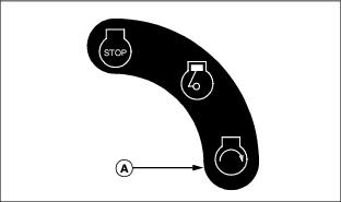
4. Turn key switch to the start position (A).
Testing Park Brake
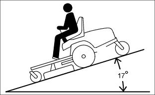
1. Stop front mower on a maximum 17° slope. Stop the engine and lock the park brake.
Starting the Engine
2. Open the fuel shut-off valve.
4. Move both control levers to the swing-out neutral position.
5. Sit on the operator's seat.
NOTE: Check position of machine PTO switch. Switch knob must be pushed down to the off position to start engine.
7. Move throttle lever to set engine speed:
· Cold engine: Pull knob up to the choke position.
· Warm/Hot engine: If necessary, pull up knob to choke position.
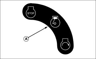
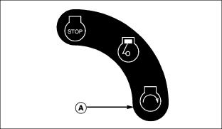
9. Turn key switch to the run position (A).
NOTE: The battery indicator light (B) may illuminate if battery voltage is low.
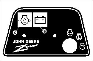
10. Check that the engine oil pressure indicator light (C) illuminates.
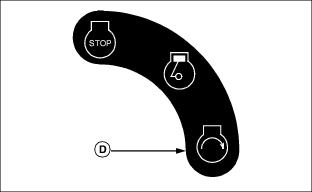
11. Turn key switch to the start position (D). Release key when the engine starts.
· Push choke knob to the off position.
· Move throttle lever to the desired engine speed.
Stopping the Engine
1. Move control levers to the swing-out neutral position.
2. Move throttle lever to a 1/2 - fast position.
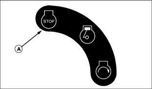
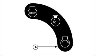
3. Turn key switch to STOP position (A).
Using the Throttle Lever
Push lever (A) all the way forward to fast position. Use this position when you mow.
Pull lever (A) to rear to slow position. Do not run engine at slow idle any longer than necessary.
Move lever (A) to the 1/2 to full fast position when stopping the engine.
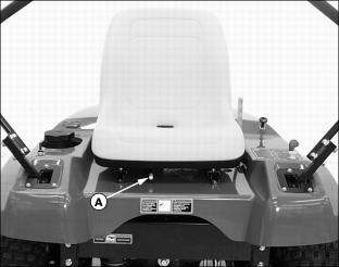
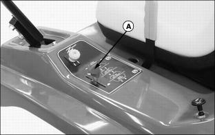
Using the Hour Meter
NOTE: The machine is equipped with an electric start. The hour meter digital display will not illuminate or operate with the key switch in the STOP position. The hour meter digital display will illuminate and continue to operate when the key switch is left in the run position.
The hour meter (A) shows number of hours the machine has run.
The service interval chart gives necessary service intervals.
Use the hour meter and service interval chart to determine when machine will need service.
Using the PTO Switch Knob
Engage PTO:
1. Move throttle lever (A) to the 1/2 to 3/4 fast position.
3. Move throttle lever (A) forward to the fast position for mowing.
Disengage PTO:
Check Indicator Lights
Oil Pressure Indicator
IMPORTANT: Avoid damage! If the indicator lights red when the engine is running, stop the engine immediately or the engine may be seriously damaged from lack of lubrication. |
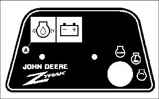
· The red indicator light (A) means the oil is low and/or the oil pressure is low.
· The indicator should illuminate when the key switch is turned to the run position.
· The light should go out when the engine starts.
Battery Indicator
IMPORTANT: Avoid damage! If the indicator lights yellow when the engine is running, stop the engine. Find and correct the cause or the battery will lose power. |
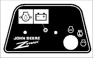
· The yellow indicator light (B) means the battery is not getting enough charge from the alternator.
· If the battery voltage is low enough, the light will illuminate.
· If the battery is fully charged, the light will not come on.
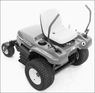
Using the Park Brake Lever
Lock park brake or use as emergency stop:
1. Raise park brake lever (A) to lock park brake.
Unlock park brake:

· Lower park brake lever (A) to unlock park brake.
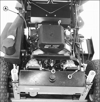
Using Free-Wheeling Levers
IMPORTANT: Avoid damage! Prevent transmission damage. Do not tow the machine, push machine by hand only. |
When the machine needs to be moved without starting the engine, use the free-wheeling levers.
1. Park machine safely. (See Parking Safely in the Safety section.)
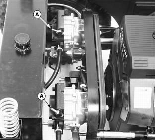
3. Turn both free-wheeling levers (A) counterclockwise approximately two revolutions.
6. Push machine to desired location. Due to transmission gear reduction, machine will move slowly.
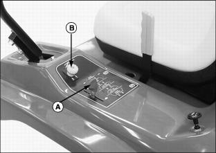
Using Fuel Shut-Off Valve
2. Open the fuel shut-off valve:
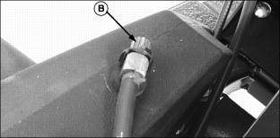
· Arrow on knob should face upward as shown in position (B) for fuel flow to be open.
3. Close the fuel shut-off valve:
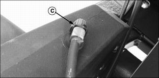
· Arrow on knob should be turned downward as shown in position (C) for fuel flow to be closed.
Using the Control Levers
The functions of the control levers are:
· Operates as a dual function neutral position.
· Controls forward speed and reverse motion.
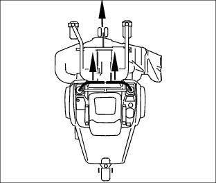
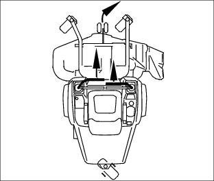
Swing-Out Neutral Position
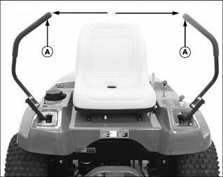
Picture Note: Control levers shown in the swing-out neutral position.
· Control levers (A) must be in the swing-out neutral position and the park brake locked to start the engine.
· Forward and reverse movement of the control levers is prevented when control levers are in a swing-out neutral position.
· Operator can exit front mower with the engine running when the control levers are in the swing-out neutral position and the park brake is locked.
· Control levers must be in the swing-out neutral position to safely enter and exit the operator seat.
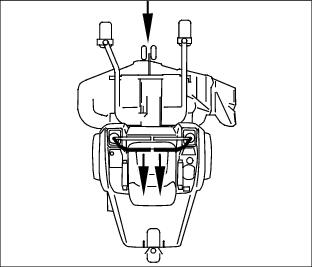
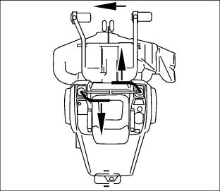
Centered Neutral Position
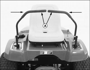
Picture Note: Control levers shown in the centered neutral position.
· Front mower speed, motion, and direction can be controlled when the engine is running, control levers (A) are in the centered neutral position, and the park brake is unlocked.
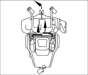
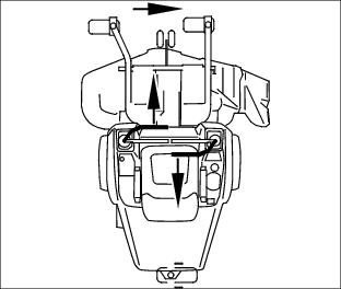
Forward and Reverse Motion:
1. Move throttle lever to the fast position.
3. Move both control levers (A) from swing-out neutral inward.
4. Push the control levers forward to move the front mower forward. Pull the control levers past center rearward at the same time to move the front mower in reverse.
· The further forward the control levers are moved, the faster the front mower will travel.
Speed Range
· Forward: 0-13.2 km/h (0-8.2 mph).
· Reverse: 0-6.5 km/h (0-4 mph).
To stop forward or reverse motion, pull or push both control levers back until machine comes to a complete stop.
Forward Travel:
· Push both control levers forward at the same time.
Reverse Travel:
· Pull both control levers past center rearward at the same time.
Gentle Left Turn:
· Push right control lever further forward than the left control lever.
Gentle Right Turn:
· Push left control lever further forward than the right control lever.
Sharp Left Turn
· Push right control lever forward and pull left control lever rearward at the same time.
Sharp Right Turn
· Push left control lever forward and pull right control lever rearward at the same time.
Transporting Machine
1. Use a heavy-duty trailer to transport your machine.
2. Back front mower with attachment onto a trailer.
3. Stop engine and lock park brake.
4. Turn the fuel shut-off valve to the off position.
5. Fasten machine to trailer with heavy-duty straps, chains, or cables. Both front and rear straps must be directed down and outward from machine.