![]()
Introduction
Product Identification
Safety
Operating
Replacement Parts
Service Intervals
Service Lubrication
Service Engine
Service Transmission
Service Steering & Brakes
Service Electrical
Cleaning Battery and Terminals
Checking Battery Electrolyte Level (Battery Not Sealed)
Checking the Battery (Sealed Batteries)
Removing and Installing the Battery
Replacing the Starting Circuit Fuse
Replacing Indicator Light Bulb
Service Miscellaneous
Troubleshooting
Storage
Assembly
Specifications
Warranty
John Deere Quality Statement
Service Record
Copyright© Deere & Company

Service Electrical
Battery
Cleaning Battery and Terminals
1. Disconnect and remove battery.
2. Wash battery with solution of four tablespoons of baking soda to one gallon of water. Be careful not to get the soda solution into the cells.
3. Rinse the battery with plain water and dry.
4. Clean terminals and battery cable ends with wire brush until bright.
6. Attach cable clamps to battery posts.
7. Apply petroleum jelly or silicone spray to terminal to prevent corrosion.
Checking Battery Electrolyte Level (Battery Not Sealed)
1. Remove battery manifold caps).
IMPORTANT: Avoid damage! Acid may leak from the battery while it is charging. Make sure the battery is filled correctly. |
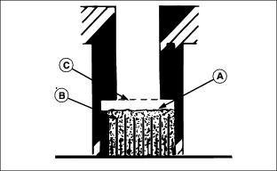
2. Check electrolyte level. Electrolyte level (A) should be halfway between the plates (B) and the filler neck (C).
3. Add distilled water if necessary.
5. Tighten battery cable hardware.
Checking the Battery (Sealed Batteries)
Battery electrolyte contains sulfuric acid. It is poisonous and can cause serious burns: · The battery produces a flammable and explosive gas. Do not smoke near battery. |
NOTE: Do not attempt to open, add fluid or service battery. Any attempt to do so will void warranty.
·Keep battery and terminals clean.
IMPORTANT: Avoid damage! This battery comes fully charged. If the mower is not used by the service expiration date indicated on the battery, charge the battery. |
·Recharge, if necessary, at 6-10 amperes for 1 hour.
Removing and Installing the Battery
· Wear eye protection and gloves. · Do not allow direct metal contact across battery posts. |
Removing:
1. Park machine safely. (See Parking Safely in the Safety section.)
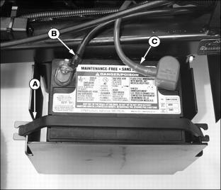
3. Disconnect rubber hold-down strap (A).
4. Remove negative (-) cable (B) from the battery first.
5. Remove positive (+) cable (C).
Installing:
1. Install battery with positive (+) post to the rear.
2. Apply petroleum jelly on battery terminals to help prevent corrosion.
3. Connect positive (red) cable (C) to battery first, then the negative (black) cable (B).
4. Install rubber hold-down strap.
Using Booster Battery

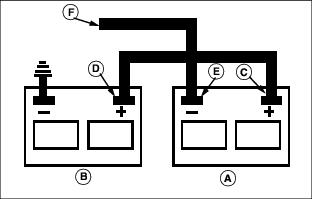
1. Connect positive (+) booster cable to booster battery (A) positive (+) post (C).
2. Connect the other end of positive (+) booster cable to the disabled vehicle battery (B) positive (+) post (D).
3. Connect negative (-) booster cable to booster battery negative (-) post (E).
4. Connect the other end (F) of negative (-) booster cable to a metal part of the disabled machine frame away from battery.
5. Start the engine of the disabled machine and run machine for several minutes.
6. Carefully disconnect the booster cables in the exact reverse order: negative cable first and then the positive cable.
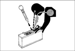
Replacing the Starting Circuit Fuse
IMPORTANT: Avoid damage! Help prevent front mower circuit damage. Make sure replacement fuse is the correct 20 amp size. |
1. Park machine safely. (See Parking Safely in the SAFETY section.)
NOTE: It may be necessary to remove cap screw (B) and the fuse holder from the cowling frame to open fuse holder.
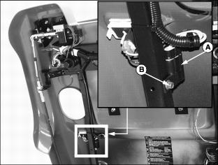
3. Open fuse holder (A) to locate the 20 amp starter fuse.
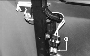
4. Replace defective fuse (B).
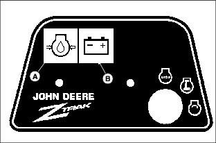
Replacing Indicator Light Bulb
If an indicator light does not illuminate, bulb replacement may be necessary. If bulb replacement does not solve the problem or if indicator lights are not functional, see a John Deere dealer.
1. Indicator light identification:
2. Park machine safely. (See Parking Safely in the SAFETY section.)
NOTE: Make sure individual bulb sockets are installed in the correct position if removal is required.
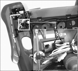
4. Turn bulb socket (C) left to remove.
5. Pull defective bulb from socket.