![]()
Introduction
Product Identification
Safety
Operating
Replacement Parts
Service Intervals
Service Lubrication
Service Engine
Engine Warranty Maintenance Statement
Changing Engine Oil and Filter
Cleaning Engine Oil Cooling Fins
Cleaning Engine Air Intake Screen
Checking and Cleaning Precleaner and Air Cleaner Element
Checking and Adjusting PTO Clutch
Service Transmission
Service Steering & Brakes
Service Electrical
Service Miscellaneous
Troubleshooting
Storage
Assembly
Specifications
Warranty
John Deere Quality Statement
Service Record
Copyright© Deere & Company

Service Engine
Engine Warranty Maintenance Statement
Maintenance, repair, or replacement of the emission control devices and systems on this engine, which are being done at the customers expense, may be performed by any nonroad engine repair establishment or individual. Warranty repairs must be performed by an authorized John Deere dealer.
Adjusting Carburetor
NOTE: The carburetor is calibrated by the engine manufacturer and should not require any adjustments.
Possible engine surging will occur at high rpm when the transmission is in neutral ("N") and the PTO switch is in the OFF position. This is a normal condition due to the emission control system.
If engine is hard to start or runs rough, check the TROUBLESHOOTING section of this manual.
After performing the checks in the troubleshooting section and your engine is still not performing correctly, contact your John Deere dealer.
Avoid Fumes

- If it is necessary to run an engine in an enclosed area, use an exhaust pipe extension to remove the fumes. |
Engine Oil
Use oil viscosity based on the expected air temperature range during the period between oil changes.
The following John Deere oils are preferred:
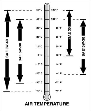
· TORQ-GARD SUPREME® (SAE 5W-30)
The following John Deere oils are also recommended, based on their specified temperature range:
Other oils may be used if above John Deere oils are not available, provided they meet one of the following specifications:
· SAE 5W-30-API Service Classification SG or higher
· SAE 10W-30-API Service Classification SG or higher
· SAE 30-API Service Classification SC or higher
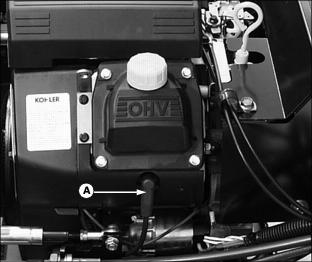
Check Engine Oil Level
1. Park machine safely. (See Parking Safely in the Safety section.)
3. Clean area around dipstick prior to removing it.
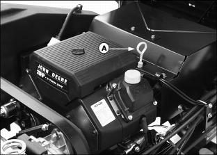
4. Remove dipstick (A). Wipe it clean.

6. Remove dipstick. Check oil level on dipstick; oil level should be between ADD and FULL (B).
· If oil is low, add oil to bring oil level no higher than the FULL mark on dipstick.
· If oil level is above the FULL mark, drain to proper level.
IMPORTANT: Avoid damage! To prevent extensive engine wear or damage, always maintain the proper engine oil level. Never operate the engine with the oil level below the add mark or over the full mark. |
Changing Engine Oil and Filter
2. Park machine safely. (See Parking Safely in the Safety section.)
4. Locate the oil drain plug and oil filter under the right side of the engine.
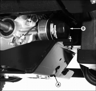
5. Remove oil drain plug (A). Allow oil to drain into a oil drain pan.
6. Remove oil filter (B). Turn filter left to remove.
7. Apply a film of clean engine oil on gasket of new filter.
8. Install filter. Turn filter right until gasket makes contact with mounting surface. Tighten 1/2 to 3/4 turn after gasket contact.
9. Install oil drain plug. Do not overtighten.
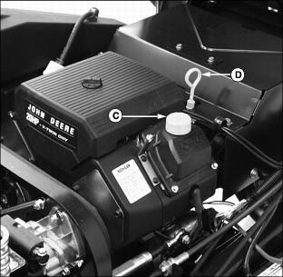
10. Clean area around the oil fill cap (C) and oil dipstick (D).
11. Unscrew and remove the oil fill cap. Add approximately 1.4 L (1.5 qt) of oil.
12. Install and tighten oil fill cap.
13. Start engine and run at slow throttle for approximately two minutes. Check for leaks around filter and drain plug.
15. Remove and wipe oil dipstick clean with a rag.

17. Remove dipstick. Oil level should be between ADD and FULL (E). Add oil if necessary.
Checking Spark Plugs
Touching hot surfaces can burn skin. The engine and components will be hot if the engine has been running. Allow the engine to cool before servicing. |
1. Park machine safely. (See Parking Safely in the Safety section.)
3. Clean area around both spark plugs.
4. Disconnect the spark plug wire (A) from each plug.
5. Remove and inspect spark plugs:
· Clean each plug and check for damage, replace if necessary.
· If plugs are in good condition, check gap.
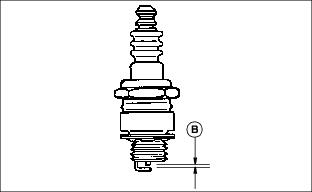
6. Check and adjust spark plug gap (B) to 1.02 mm (0.040 in.).
7. Install spark plugs and tighten to 24-30 N·m (1822 ft-lb).
8. Install both spark plug wires.
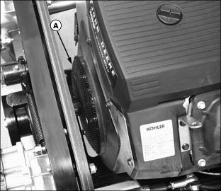
Cleaning Engine Oil Cooling Fins
IMPORTANT: Avoid damage! Prevent engine overheating. Keep the cooling fins and other external surfaces of the engine clean at all times. |
1. Park machine safely. (See Parking Safely in the Safety section.)
3. Clean engine oil cooling fins (A) with a rag, brush, or compressed air.
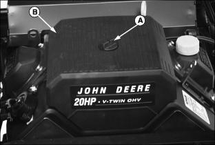
Cleaning Engine Air Intake Screen
IMPORTANT: Avoid damage! Prevent engine overheating. Keep the cooling fins and other external surfaces of the engine clean at all times. |
1. Park machine safely. (See Parking Safely in the Safety section.)
3. Clean engine screen (A) with a rag, brush or compressed air.
Cleaning Engine Cooling Fins
IMPORTANT: Avoid damage! Prevent engine overheating. Keep the cooling fins and other external surfaces of the engine clean at all times. |
1. Park machine safely. (See Parking Safely in the Safety section.)
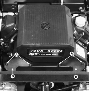
3. Remove cap screws (A) and front clean out plates (B) from each side of engine.
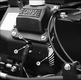
4. Remove spark plug wire (C) from each engine spark plug.
5. With compressed air, thoroughly clean grass buildup and debris from the following areas:
· Head cooling passage behind each front cleanout plate (B).
· Area (D) behind each spark plug access hole.
· Area (E) between the rear of the engine and the heat shield on each side of the engine.
6. Install front clean out plates.
Checking and Cleaning Precleaner and Air Cleaner Element
NOTE: It may be necessary to check the air filter more frequently if operating vehicle in dusty conditions.
1. Park machine safely. (See Parking Safely in the Safety section.)
3. Loosen air cleaner cover retaining knob (A) and remove the cover (B).
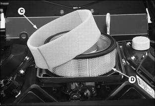
4. Inspect foam precleaner (C) without removing.
NOTE: Do not wash paper element.
5. If foam precleaner is dirty, carefully remove from filter, leaving paper element (D) in the air cleaner housing:
· Wash foam precleaner in a solution of warm water and liquid detergent. Squeeze out excess water in a dry cloth until precleaner is completely dry. (Do not wring.)
· Put approximately 30 ml. (1 oz.) of clean engine oil onto precleaner. Squeeze precleaner to distribute oil evenly. Squeeze out excess oil with a clean cloth.
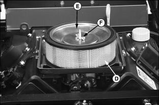
6. Inspect and replace paper filter element (D) only if damaged or very dirty.
7. Remove element cover wing nut (F) and cover (E) and remove paper element.
8. Install cleaned foam precleaner and new paper element.
9. Install element cover and wing nut.
10. Install air cleaner cover and retaining knob.
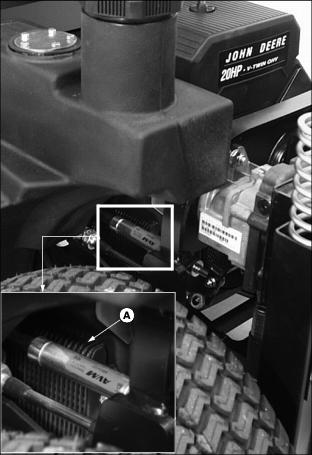
Replace Fuel Filter
Keep cigarettes, sparks, and flames away from the fuel system. Make sure engine is cool to the touch. |
1. Park machine safely. (See Parking Safely in the Safety section.)
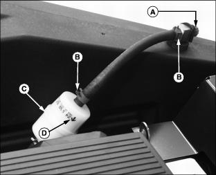
3. Turn fuel shut-off valve (A) to the closed position.
4. Slide hose clamps (B) away from filter (C).
5. Place a drain pan or rag under hoses to catch any fuel that may be left in the hoses.
6. Disconnect hoses from filter.
IMPORTANT: Avoid damage! When installing a new fuel filter, the filter arrow (D) must be pointed in the direction of the fuel flow. |
8. Connect hoses to new filter.
10. Turn fuel shut-off valve (A) to the open position.
Checking and Adjusting PTO Clutch
NOTE: Mower deck attachment must be installed when performing this service procedure.
Clear area of all bystanders before performing this service procedure. Keep hands and feet away from mower blades and discharge opening. |
Check Mower Blade Stop Time
1. Park machine on a hard, level surface.
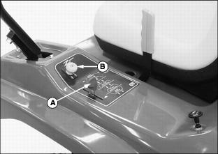
3. Set throttle lever (A) to the 1/2 fast position.
4. Pull up PTO knob (B) to engage mower.
5. Move throttle lever to the fast position.
6. Push down PTO knob to disengage mower.
7. Visually check movement of mower deck drive belt and record the number of seconds required for the belt to stop rotating.
8. Check drive belt tension adjustment if belt stop time exceeds six seconds.
Checking Drive Belt Tension Adjustment
Prevent entanglement in belt or pulley. Stop engine and wait for all moving parts to stop before servicing the machine. |
2. Lower mower deck to lowest cutting height.
3. Pivot the right mower deck footrest completely forward.
NOTE: Locknuts (A) and (B) must be loosened prior to measuring the spring length or an inaccurate measurement will be obtained.
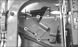
4. Loosen locknuts (A) and (B).
5. Measure tension spring length (C). If spring length is not 133mm (5.25 in.), a drive belt tension adjustment is required. If the spring length is adjusted correctly, proceed to the PTO clutch adjustment procedure.
Adjusting Drive Belt Tension
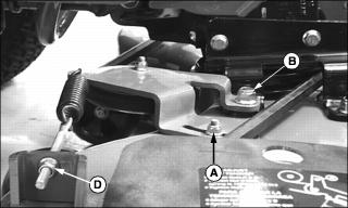
1. Tighten or loosen adjustment nut (D) as needed until spring length is 133mm (5.25 in.).
2. Tighten locknut (A) to 28 N·m (20 lb-ft).
3. Tighten locknut (B) to 95 N·m (70 lb-ft).
4. Lower right mower deck footrest.
5. Check mower blade stop time. If belt stop time still exceeds 6 seconds, a PTO clutch adjustment is required.
Adjusting the PTO Clutch
Prevent entanglement in belt or pulley. Stop engine and wait for all moving parts to stop before servicing the machine. |
3. Disconnect the spark plug wires.
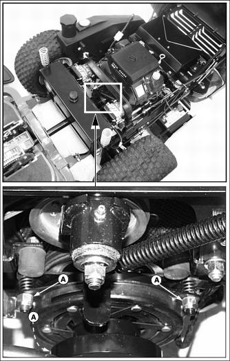
4. Mark location of nuts (A) before beginning the adjustment procedure.
Do not overtighten PTO clutch adjusting nuts. Overtightening nuts will prevent clutch disengagement allowing the mower blades to turn continuously. |
NOTE: All clutch adjustment nuts must be turned equally.
Tightening the adjustment nuts reduces the air gap between the clutch rotor and brake plate, reducing time needed for brake engagement. Loosening the adjustment nuts increases the air gap between the clutch rotor and brake plate, increasing time needed for brake engagement.
5. Turn each nut (A) 1/2 turn clockwise.
6. Check mower blade stop time. If stop time exceeds 5 seconds, stop engine and turn each adjusting nut clockwise an additional 1/4 turn.
IMPORTANT: Avoid damage! If contact between the clutch rotor and brake plate is detected, stop engine and loosen adjustment nuts 1/4 turn. |
7. Check mower blade stop time. Continue adjustment procedure until mower blade stop time is between 3 and 5 seconds.