![]()
Introduction
Product Identification
Safety
Operating
Replacement Parts
Service Intervals
Service Lubrication
Service Engine
Service Transmission
Service Steering & Brakes
Service Electrical
Service Miscellaneous
Troubleshooting
Storage
Assembly
Specifications
Warranty
John Deere Quality Statement
Service Record
Copyright© Deere & Company

Assembly
Bag of Parts List
NOTE: Drive wheels and rear wheel assembly are ordered and shipped separately.
Prepare for Assembly
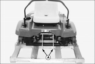
1. Cut two plastic tie straps (A) securing cowling to the machine frame.

2. Cut steel bands securing rear of machine to shipping crate pedestal.
Install Rear Wheel Assembly
Use a safe lifting device to prevent injury from a falling vehicle. |
1. Raise rear of machine with a safe lifting device.
2. Remove wood pedestal from shipping crate.
3. Check rear wheel tire inflation pressure(s).
· Keep tire(s) inflated to 110 kPa (16 psi).
NOTE: Both locknuts that attach bottom of wheel mounting bracket to the rear of the front mower are welded inside the frame.
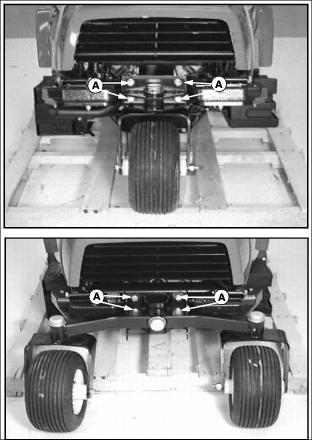
Picture Note: Top photo shows single rear wheel assembly installed. Bottom photo shows dual rear wheel assembly installed.
4. Install rear wheel assembly to front mower using four M12x30 flanged hex screws (A) and two M12 locknuts.
Install Front Drive Wheels
Use a safe lifting device when performing this assembly procedure to prevent injury from a falling vehicle. |

2. Loosen five wheel bolts (A) stored in each drive wheel hub.
3. Remove hardware (B) securing brackets (C) to bottom of shipping crate base.
4. Lift front of machine with a safe lifting device.
5. Remove shipping crate base from under machine.
6. Remove wheel bolts and shipping brackets. Dispose of shipping brackets.
7. Check drive wheel tire inflation pressures:
· Keep tires inflated to 69 kPa (10 psi).
8. Attach one wheel to each hub using five wheel bolts, tighten until snug.
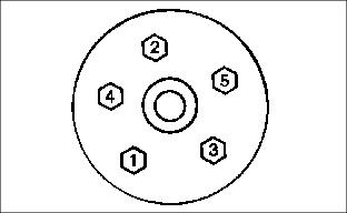
· Tighten wheel bolts in numbered sequence shown for safe wheel installation. Tighten alternately until recommended torque value is reached.
· Tighten bolts to 100 N·m (75 lb-ft.).
Connect the Battery

2. Connect red positive (+) cable (A) to battery with one M6x16 screw (B) and one M6 flanged hex nut (C). Apply petroleum jelly or silicone spray to terminal to prevent corrosion. Make sure connection is tight. Install the red terminal cover.
3. Connect black negative (-) cable (D) to battery with one M6x16 screw (B) and one M6 flanged hex nut (C). Apply petroleum jelly or silicone spray to terminal to prevent corrosion. Make sure connection is tight.
Delivery Instructions
Prior to delivery, perform the listed service checks, clean the machine and review this manual with the owner/operator. Make sure the owner/operator can safely operate this machine.
Check Safety Interlock System
For a complete checkout procedure of the safety interlock system, see Testing the Safety Interlock System in the Operating section.
Check Tire Pressure
For complete information on tire safety, see Tire Safety in the Safety section. See the Specifications Section for recommended tire pressures.
Check Wheel Hardware Torque
For complete instructions and specifications on how to properly torque the wheel bolts, see Tightening Wheel Hardware in the Service Miscellaneous section.
Check Fluid Levels
Check Engine Oil Level
Oil level should be between the ADD and FULL marks on the dipstick. Add oil as necessary. See Check Engine Oil Level in the Service Engine section for additional information.
Check Hydraulic Oil Level
Hydraulic oil level should be to the top of the FULL COLD mark on the reservoir dipstick. Add oil as necessary. See Check Hydraulic Oil Level in the Service Transmission section.
Check Mower Deck Level
After front mower is completely assembled and the mower deck is installed, check the mower deck level. Refer to the Operating section in the mower deck operator's manual for instruction on how to check and adjust mower deck level.
Break-In Electric PTO Clutch
Before engaging mower, clear area of bystanders, especially children. |
NOTE: This break-in procedure must be done with the mower deck installed.
2. Set throttle lever to the 1/2 fast position.
3. Engage PTO switch knob and allow machine to run for 10 seconds.
4. Disengage PTO switch knob and wait 10 seconds.
5. Repeat step three 12-15 times to properly burnish the PTO clutch.