![]()
Introduction
Product Identification
Safety
Operating
Replacement Parts
Service Intervals
Service Lubrication
Service Engine
Service Transmission
Service Steering & Brakes
Remove and Install Front Wheels
Remove and Install Rear Wheel(s)
Checking and Aligning Control Levers
Service Electrical
Service Miscellaneous
Troubleshooting
Storage
Assembly
Specifications
Warranty
John Deere Quality Statement
Service Record
Copyright© Deere & Company

Service Steering & Brakes
Remove and Install Front Wheels
Removing:
1. Park machine safely. (See Parking Safely in the Safety section.)
2. Slightly loosen five wheel bolts (A).
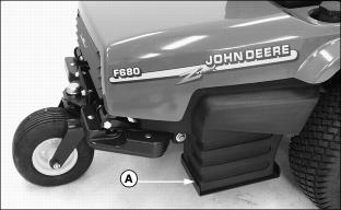
· For right side, locate the jack centered under portion of engine base supporting the fuel tank (A).
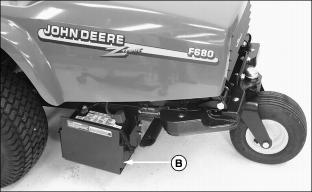
· For the left side, locate the jack centered under portion of engine base supporting the battery (B).
Installing:
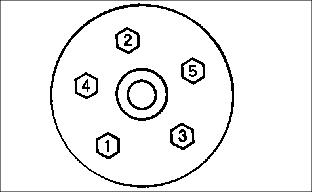
3. Tighten wheel bolts in numbered sequence shown for safe wheel installation. Tighten bolts alternately until bolts are tightened to 100 N·m (75 lb-ft).
Remove and Install Rear Wheel(s)
Removing
1. Park machine safely. (See Parking Safely in the Safety section.)
2. Align rear wheel(s) so they are pointing straight ahead.
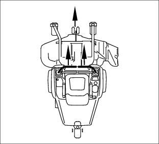
3. Lift rear of front mower with a safe lifting device.
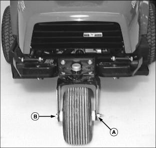
Picture Note: Photo shows front mower equipped with the single rear wheel option.
4. Remove hex nut (A), wheel bolt (B).
5. Remove wheel from assembly yoke.
6. Remove steel spacer from wheel hub.
Installing
1. Install steel spacer into replacement wheel hub.
2. Install wheel bolt and hex nut.
Checking and Aligning Control Levers
Check Alignment:
1. Park machine safely. (See Parking Safely in the Safety section.)
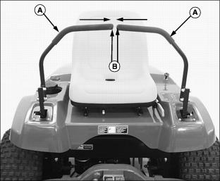
2. Move both control levers (A) inward to the centered neutral position.
3. Check control levers for equal height and forward and rearward alignment. The gap (B) between the levers should be approximately 6 mm (1/4 in.).
· If positions of the control levers are unequal, an adjustment is necessary.
Height Gap Adjustment
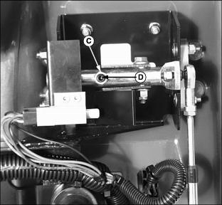
· To increase gap, turn set screw (D) clockwise.
· To decrease gap, turn set screw (D) counterclockwise.
Forward and Rearward Adjustment
3. Adjust control levers forward or rearward until both control levers are aligned.
4. Check adjustment. Repeat adjustment if necessary.
Adjusting Park Brake
Adjust Park Brake-Primary Adjustment
1. Park front mower on a hard, level surface.
NOTE: Park brake lever must be unlocked and in thposition prior to performing a park brake adjustment.
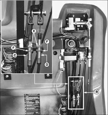
5. Locate primary park brake adjustment assembly (B) under left side of cowling.
IMPORTANT: Avoid damage! Left and right wheel brake adjustments must be done evenly to accomplish satisfactory park brake performance and prevent uneven brake wear. |
· To decrease brake tension, turn bottom jam nut counterclockwise.
· To increase brake tension, turn bottom jam nut clockwise.
12. Move throttle lever to the fast position.
13. Move both control levers to the centered neutral position. Push both control levers forward.
· Drive wheels should start to turn freely and front mower should begin to travel forward.
· Brakes are adjusted too tight if an audible hydrostatic whine is detected and the front mower does not move.
14. Test and adjust brakes as necessary.
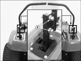
Adjust Park Brake-Secondary Adjustment
NOTE: Make park brake secondary adjustment only when the primary adjustment has been completely used up.
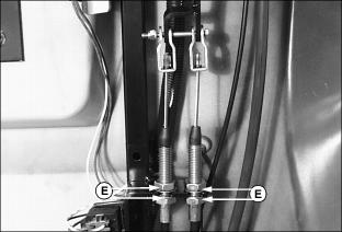
2. Loosen upper and lower jam nuts (E).
3. Turn both bottom jam nuts fully to the bottom of the primary adjustment assembly.
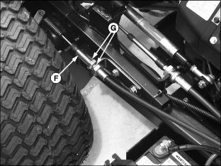
4. Locate park brake secondary adjustment (F) on each side of the front mower.
5. Loosen secondary adjustment jam nuts (G).
6. Turn jam nuts 6mm (1/4 in.) forward on each adjustment cable.
8. Make a park brake primary adjustment and tighten jam nuts (E).
9. Test and adjust brakes as necessary.
Adjust Tracking
A proper tracking adjustment will allow the front mower to maintain a straight line direction of travel.
Right and left transmission speeds will vary with travel speed and RPM variations.
NOTE: To improve straight line tracking, drive wheel tire pressures must be equal.
Check Tracking
3. Move both control levers to the centered neutral position.
4. While holding both control levers together, push both control levers forward to a desired mowing speed.
· If the front mower travels to the right or left, an adjustment is required.
Adjust Tracking
1. Park machine safely. (See Parking Safely in the Safety section.)
2. Move both control levers to the centered neutral position.
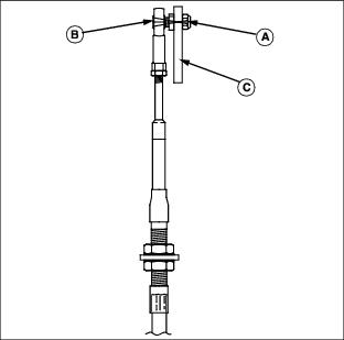
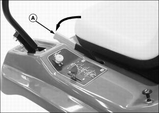
4. Loosen locknut (A) fastening steering cable eyebolt (B) to slotted control arm plate (C).
· If the front mower moves to the left, adjust right control lever.
· If the front mower moves to the right, adjust left control lever.

5. Slide cable rod end (D) inside control arm plate adjustment slot (E).
· Cable rod end should be slid up (toward seat) in the adjustment slot to slow down the faster transmission pump.
· Adjustments should be done in 6mm (1/4 in.) or less increments.
8. Check tracking adjustment. Continue the adjustment process until the front mower travels in a desirable straight line direction.