![]()
1200A Bunker and Field Vehicle
Introduction
Safety
Controls
Operating
Replacement Parts
Service Machine Safely
Service Intervals
Service Engine
Service Transmission
Service Steering & Brakes
Service Electrical
Service Miscellaneous
Troubleshooting
Assembly
Specifications
Warranty
John Deere Quality Statement

Assembly
Activate Battery
IMPORTANT: Avoid damage! To prevent damage to tractor from spilled electrolyte, remove the battery from the tractor. |
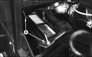
2. Remove nuts (A) and protective cover.
3. Disconnect negative (-) (black) cable from the battery .
4. .Disconnect the positive (+) (red) cable next.
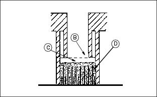
· Only use battery acid with a 1.265 specific gravity. Slowly add acid (C) to each cell. The solution should be 1/4 in. (6 mm) above plates (D), but NO HIGHER THAN 6 mm (1/4 in.) from the bottom of the filler neck (B).
IMPORTANT: Avoid damage! Wait 20 minutes before charging the battery to allow the plates to "absorb" the acid so they take a charge well. |
7. Charge the battery for a MINIMUM of four hours at 4 amps or until specific gravity is 1.250. If your battery charger has a Deep Cycle or Maintenance Free setting, use this setting to charge the battery. Failure to charge the battery before use will reduce battery performance and life.
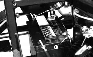
9. Connect red positive (+) cable (E) to battery. Apply petroleum jelly or silicone spray to terminal to prevent corrosion. Make sure connection is tight.
10. Connect black negative (-) cable (F) to battery. Apply petroleum jelly or silicone spray to terminal to prevent corrosion. Make sure connection is tight.
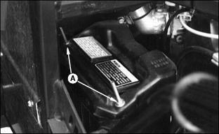
11. Install protective covering over battery. Fasten using nuts (C).
NOTE: DO NOT over tighten screws, it may break plastic cover.
Install Steering Wheel
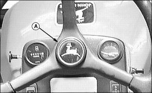
2. Remove nut from steering bolt and install steering wheel. Fasten using nut and tighten to 33 N·m (24 lb ft.).
3. Install cap (A) in center of steering wheel.
Install Tires
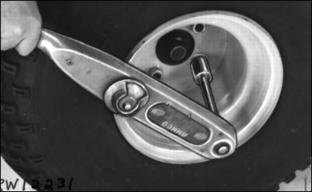
1. Inflate tires to 34-41 kPa (4-6 psi).
2. Remove nuts from wheel axle bolts.
3. Lift machine high enough to install tires.
NOTE: Valve stem must be to the outside of machine.
4. Fasten tires using nuts. Tighten to 80 N·m (60 lb ft.).
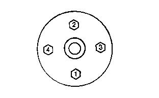
5. Beveled sides must face inward. Tighten in sequence illustrated, alternately and evenly until recommended torque is reached.
Checking Tire Pressure

2. Check tire pressure with an accurate low pressure gauge.
Connect Lift Actuator
NOTE: The lift actuator, located on the left side of the rear vehicle frame can be positioned two different ways for different functions.
NOTE: Bunker or field rake position (A) and field finisher (B).
NOTE: Machine is shipped in the rake position.
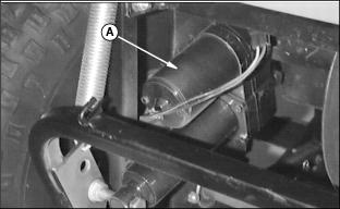
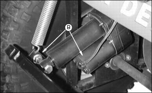
1. Remove tie strap from cylinder.
2. Remove outside nut (C) (not shown here) from bolt (D) at rod end of cylinder.
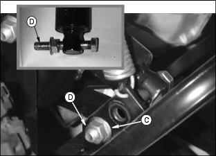
3. Place bolt (D) in front hole on rear frame bracket and secure with nut (C) removed earlier, torque to 81 N·m (60 lb-ft).
Install Seat
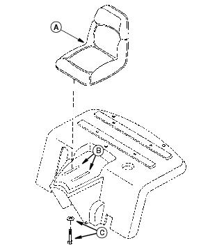
1. Remove the four cap screws and washers that are in the seat.
2. Place the seat (A) over the slots (B) on the rear hood.
3. Install cap screws and washers (C) as shown and tighten
NOTE: The seat can be adjusted along the length of the slots by loosening the cap screws and sliding
the seat to desired position.