![]()
2653 Professional Utility Mower
Introduction
Safety Signs
Controls
Operating Machine
Operating Cutting Unit
Replacement Parts
Service Machine Safely
Service Intervals
Service Lubrication
Service Engine
Engine Warranty Maintenance Statement
Changing Engine Oil And Filter
Cleaning Air Intake Screen And Radiator
Checking And Cleaning Air Cleaner Elements
Tightening Or Replacing Fan Belt
Service Transmission
Service Cutting Units
Service Electrical
Service Miscellaneous
Troubleshooting
Storing Utility Mower
Assembly
Copyright© Deere & Company

Service Engine
Engine Warranty Maintenance Statement
Maintenance, repair, or replacement of the emission control devices and systems on this engine, which are being done at the customers expense, may be performed by any nonroad engine repair establishment or individual. Warranty repairs must be performed by an authorized John Deere dealer.
Avoid Fumes
· If it is necessary to run an engine in an enclosed area, use an exhaust pipe extension to remove the fumes. |
Engine Oil
Use oil viscosity based on the expected air temperature range during the period between oil changes.
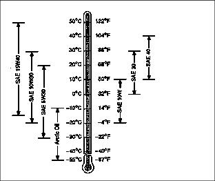
The following oil is preferred:
Other oils may be used if they
· API Service Classification SG
· API Service Classification SF
Checking Engine Oil
1. Park vehicle on a level surface.
2. Check engine oil level before running machine, when oil is cold and maximum drain back has occurred.
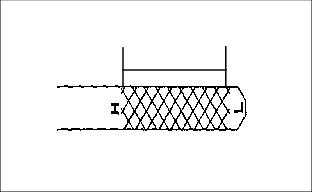
5. Check oil level on dipstick.

6. Oil level should be between FULL mark "H" and LOW mark "L" on dipstick
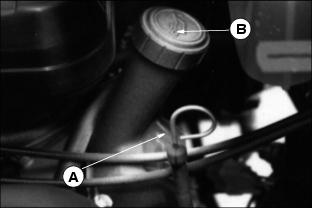
7. If oil level is low, remove oil filler cap (B).
8. Add oil to bring oil level no higher than the "H" mark on dipstick. (See ENGINE OIL in this section for correct oil.)
10. Install and tighten oil filler cap.
Changing Engine Oil And Filter
IMPORTANT: Avoid damage! Change engine oil and filter after first 50 hours of break-in operation. When operating vehicle in extremely dusty or dirty conditions, change engine oil more often. |
1. Park vehicle on a level surface.
3. Run engine a few minutes to warm oil.
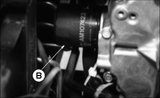
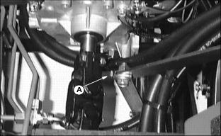
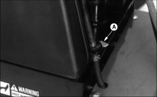
5. Place oil drain pan under drain valve (A) and oil filter (B). Open drain valve and drain oil.
6. Remove filter using a filter wrench. Turn filter counterclockwise.
7. Apply a film of clean engine oil on seal of new filter.
8. Install filter. Turn filter until seal contacts mounting surface. Then turn filter BY HAND 1/2 turn more.
10. Remove filler cap (C). Add 1.4 liters (48 oz.) of oil. (See Engine Oil for correct oil.)
12. Start engine and run at slow speed for two minutes.
13. Check for leaks around filter and drain plug.
14. Stop engine. DO NOT add more engine oil to the crankcase.
15. After operating the engine, the oil filter will be filled and the engine oil level will be near the "H" mark ) on the dipstick (D) after adequate engine oil "drain down" time.
Service Cooling System Safely
Engine Coolant
Use ethylene glycol base coolant. These coolants usually have labels stating "For Automobile and Light Duty Service." These products are also often labeled for use in aluminum engines. Check container label before using.
Engine Coolant (Continued)
IMPORTANT: Avoid damage! To prevent engine damage, DO NOT use pure antifreeze or more than 50% antifreeze in the cooling system. DO NOT mix or add any other type additives to the cooling system. |
Mix approximately 50 percent antifreeze with 50 percent distilled or deionized water. This mixture will provide freeze protection to -37 degrees C (-34 degree F).
The recommended antifreeze provides:
· Corrosion-resistant environment within the cooling system.
· Compatibility with cooling system hose and seal material.
· Protection during cold and hot weather operations.
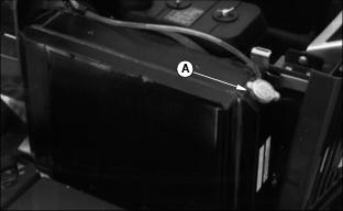
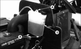
Checking Coolant Level
2. Coolant level MUST BE within WARM and COOL marks on recovery tank.
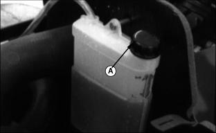
3. If coolant is low, remove coolant recovery tank cap (A).
4. Mix 50 percent ethylene glycol antifreeze with 50 percent distilled or deionized water.
5. Add mixture to coolant tank.
6. Install and tighten coolant recovery tank cap.
7. Clean debris from air intake screen and radiator. (See Clean Air Intake Screen and Radiator this section.)
8. Check condition of hoses. Check for leaks or loose connections
Cleaning Air Intake Screen And Radiator
4. Clean screen with a brush or compressed air.
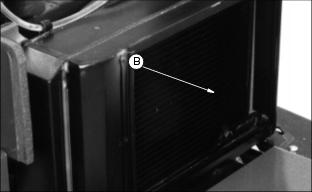
5. Clean radiator cooling fins (B) using compressed air or a brush.
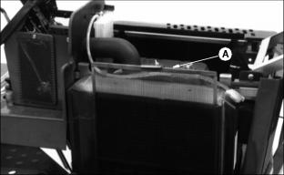
Draining Cooling System
1. Stop the engine. Let the engine cool.
4. Slowly remove radiator cap (A).
5. Open radiator petcock (B). Drain coolant into a bucket.
6. Flush cooling system if necessary (See Flushing Cooling System in this section).
7. After all coolant has drained, close radiator petcock.
8. Fill cooling system (See Filling Cooling System in this section).
Flushing Cooling System
1. Fill cooling system with clean water and PT500 John Deere Cooling System Cleaner, or PT592 John Deere Cooling System Quick Flush or an equivalent. Follow the directions on the can.
2. Install and tighten the radiator cap.
3. Start and run the engine until it reaches operating temperature.
4. Drain the cooling system immediately before rust and dirt settle. (See Draining Cooling System in this section.)
5. Remove three recovery tank screws (A) and recovery tank (B).
6. Remove tank cap and clean recovery tank.
8. Check condition of coolant system hoses and clamps.
9. Install new hoses if necessary.
10. Fill cooling system. (See Filling Cooling System in this section.)
Filling Cooling System
1. Mix 50 percent antifreeze with 50 percent distilled or deionized water. (See Engine Coolant section for type of antifreeze.)
2. Add mixture to radiator. Install and tighten radiator cap.
3. Run engine until it reaches operating temperature.
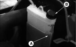
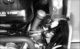
5. After engine cools, check coolant level in recovery tank (A). Level in recovery tank should be between WARM and COOL marks.
6. Remove cap (B) to add coolant mixture if necessary.
7. Check condition of coolant system hoses and hose clamps. Replace if necessary.
Checking And Cleaning Air Cleaner Elements
IMPORTANT: Avoid damage! If you operate the vehicle in dusty conditions, clean the precleaner more often. |
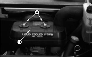
2. Remove two wing nuts (A) and cover (B).
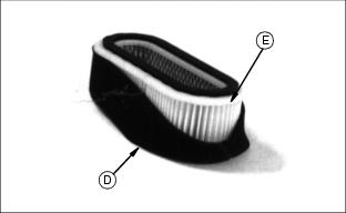
4. Check precleaner for dirt and dust. If precleaner (D) is dirty, remove from paper element (E) and clean as follows
· Wash precleaner in warm, soapy water.
· Rinse precleaner in clean water.
· Squeeze precleaner to remove most of the water.
· Apply 30 mL (1 oz.) of clean engine oil to precleaner.
· Squeeze precleaner to distribute oil evenly and remove excess oil.
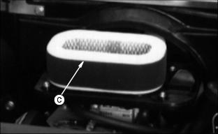
5. Check air cleaner paper element:
· If paper element is dirty, tap gently on your hand to remove dust.
· If the element is oily or very dirty or damaged, install a new element.
6. Install precleaner on paper element.
7. Install air cleaner and cover.
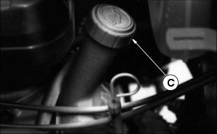
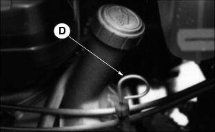
Replacing Fuel Filter
1. Stop the engine. Let it cool.
2. Close fuel shut-off valve (A).
3. Squeeze and slide hose clamps (B) away from fuel filter (C).
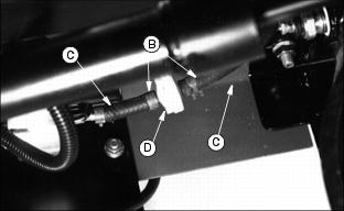
4. Remove hoses from fuel filter (D).
NOTE: Be sure arrow on fuel filter is pointed in the direction of fuel flow.
5. Connect hoses to new filter.
6. Squeeze and slide clamps over hoses against filter.
Tightening Or Replacing Fan Belt
2. Remove both engine spark plugs
NOTE: Rotate driveshaft for access to bolts, if necessary.
3. Remove three bolts (A) to disconnect driveshaft (B).
4. R remove three bolts (C) to remove outer sheave (D).
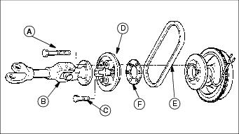
5. Remove belt (E) if it is to be replaced.
NOTE: To allow sheaves to fit closer together and increase belt tension, remove shim (F). Save spacer to use when new belt is installed.
6. Remove spacer shim (F) if belt is to be tightened. Leave spacer in if installing a new belt.
7. Loosely install belt between sheave halves and start installing the three outer sheave-retaining bolts.
8. Rotate sheave assembly as bolts are tightened to allow belt to center in sheave halves and not be pinched in an OFF- CENTER position.
Adjusting Carburetor
NOTE: Carburetor is calibrated by the engine manufacturer and should not require any adjustments.
If engine is operated at altitudes above 1829 m
(6,000 ft), some carburetors may require a special high altitude main jet. See your John Deere dealer.
Possible engine surging will occur at high rpm with no load (with transmission in "N" neutral and PTO switch in the OFF position. This is a normal condition due to the emission control system.
If engine is hard to start or runs rough, check the troubleshooting section of this manual.
After performing the checks in the troubleshooting section and your engine is still not performing correctly, contact your John Deere dealer.