![]()
2653 Professional Utility Mower
Introduction
Safety Signs
Controls
Operating Machine
Operating Cutting Unit
Replacement Parts
Service Machine Safely
Service Intervals
Service Lubrication
Service Engine
Service Transmission
Service Cutting Units
Service Electrical
Service Miscellaneous
Troubleshooting
Storing Utility Mower
Assembly
Assemble Professional Utility Mower
Copyright© Deere & Company

Assembly
Assemble Professional Utility Mower
2. Remove wires from motors and lift arms.
3. Put a jack under frame and support machine.
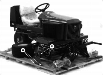
4. Remove bolts and nuts (A) holding shipping bracket (B) to skid.
5. Remove four lug bolts and shipping bracket. Retain hardware. Discard shipping bracket.
6. Raise machine, install wheel and tire using lug bolts. Torque to 81-95 N· m (60-70 lb-ft).
7. Repeat Steps 3 and 6 on opposite side.
10. Use free wheeling lever and carefully move machine off pallet. (See Using Free Wheeling Lever in the Operating Section.)
Activate Battery
IMPORTANT: Avoid damage! To prevent damage to tractor from spilled electrolyte, remove the battery from the tractor. |
1. Install a TY6182 battery (not supplied with the machine).
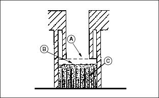
· Only use battery acid with a 1.265 specific gravity. Slowly add acid (B) to each cell. The solution should be 6 mm (1/4 in.) above plates (C), but NO HIGHER THAN 6 mm (1/4 in.) from the bottom of the filler neck (A).
3. Install the battery manifold cap.
4. Charge the battery for a MINIMUM of 30 minutes at 5-10 amps. If your battery charger has a Deep Cycle or Maintenance Free setting, use this setting to charge the battery. Failure to charge the battery before use will reduce battery performance and life.
NOTE: Battery Type U1 - 340 CCA, 12 volts.
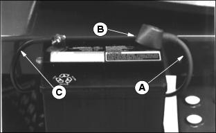
5. Connect red positive (+) cable (A) to battery. Apply petroleum jelly or silicone spray to terminal to prevent corrosion. Make sure connection is tight. Push red positive cover (B) over positive terminal.
6. Connect black negative (-) cable (C) to battery. Apply petroleum jelly or silicone spray to terminal to prevent corrosion. Make sure connection is tight.
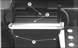
7. Install the battery cover (D). Install battery hold-down (E) and fasten with washers and wingnuts (F) below battery support bracket. Tighten wing nuts.
Install Front Roller
1. Remove cap plugs from ends of roller shaft.
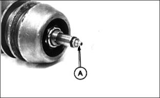
2. Insert grease zerks (A) in both ends.
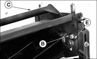
3. Install cutting unit yoke (C) using (B) 1/2 x 3 in.bolts, bushings (E), and nuts.
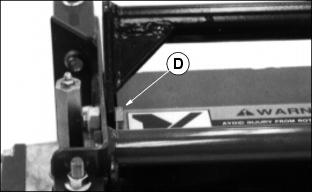
NOTE: There are two positions the yoke can be placed, float and fixed position (D), bolts and nuts provided. (See Cutting Shorter and Longer grass under Operating Cutting Units section).
The yoke for the Left Front is different and will have an (L) stamped on it to distinguish the offset to the motor side.
The reel drive motors are installed on the inboard end of both front cutting units. For the Left Front position the cast end cap will have to be moved to the opposite end of the cutting unit before installing the drive motors.
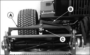
4. Install yoke (A) onto lift arm (B) using quick-lock pin (C).
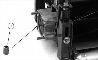
5. Put coupler (D) on motor reel shaft and install motor.
6. Repeat Steps 1-5 on the other cutting units.