![]()
2653 Professional Utility Mower
Introduction
Safety Signs
Controls
Operating Machine
Operating Cutting Unit
Replacement Parts
Service Machine Safely
Service Intervals
Service Lubrication
Service Engine
Service Transmission
Service Cutting Units
Avoid Injury From Contacting Blades
Adjusting Reel-To-Bed Knife Clearance
Readjust Reel-To-Bed Knife Clearance
Service Electrical
Service Miscellaneous
Troubleshooting
Storing Utility Mower
Assembly
Copyright© Deere & Company

Service Cutting Units
Avoid Injury From Contacting Blades
· DISENGAGE cutting units to stop reels. Keep hands, feet and clothing away from cutting units when engine is running. |
Adjusting Cutting Units
NOTE: Adjustments may affect each other. It is important that adjustments be made in the following sequence.
1. Adjust two bolt gauge bar for desired height-of-cut.
2. Set units for the height-of-cut.
3. Adjust the reel-to-bed knife clearance.
4. Perform the backlapping operation.
IMPORTANT: Avoid damage! Reel must NOT contact bed knife during normal operation or overheating and damage to both reel and bed knife may occur. |
5. Readjust reel-to-bed knife clearance.
Adjusting Height-Of-Cut
NOTE: All cutting units must be set at the same height to obtain an even cut. Floating units will not provide a quality cut in grass over approximately 38 mm (1-1/2 in.) tall.
1. Adjust reel-to-bed knife. See adjusting reel-to-bed knife in this section.
2. Raise cutting units or remove as desired.
NOTE: Rear rollers come from factory set and leveled at 19 mm (3/4 in.) cut.
If rollers are adjusted to a position so gauge bar cannot be installed, raise either the front or rear roller or both to allow installation of the gauge bar.
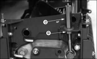
· Loosen bottom adjusting nuts (B).
· Turn top adjusting nut (C) clockwise on each end of cutting unit, alternating back and forth.
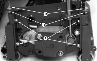
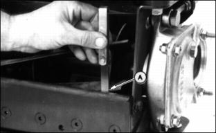
5. If adjustment is limited by slots at (A) then raise or lower each adjuster one notch as needed to every adjuster
Adjusters MUST be installed with carriage bolt in top hole (D) (stud end) for H.O.C. lower than 38 mm (1.5 in.).
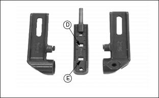
NOTE: Each notch in the adjuster rack equals 3.2 mm (1/8 in.). Set rear roller first and then front roller.
Height-Of-Cut has two general height settings 9.5-41 mm (3/8-1-5/8 in.) and 38-89 mm (1-1/2-3-1/2 in.).
· Adjusters MUST be installed with carriage bolt in the bottom hole (E) for H.O.C. greater than 1.5 in. (See front roller instruction sheet for hole selection.)
NOTE: Using a single-bolt adjusting gauge bar will not insure parallelism between rollers and may result in uneven height-of-cut.
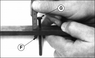
6. Loosen wing nut (F). Set height-of-cut by measuring from the top of the gauge to the bottom of the head of the bolt (G).
8. Hook head of bolt (H) over edge of bed knife. (Cutting unit is upside down for photo clarity.)
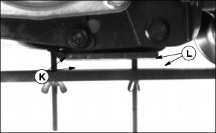
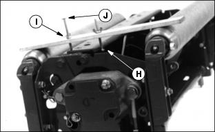
9. Loosen wing nut (I). Turn bolt (J) until gauge is parallel with bed knife. Measure distance between front (K) and rear (L) of the bottom of the bed knife to top of gauge. Distance should be the same.
NOTE: When adjusting rollers, move both ends of roller equally, alternating from end to end. This will keep the adjusters from binding
10. Loosen top adjusting nuts.
IMPORTANT: Avoid damage! DO NOT turn nuts on front adjuster beyond where the roller just touches the gauge bar or the bar will bend. |
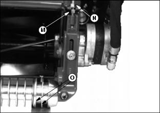
11. Grooved rollers: Carefully turn bottom adjusting nut (M), after loosening top nut (N), until the first 2 ribs (O) of the machined portion of the roller just touches the gauge.
This is determined by turning the roller and listening for the scratching sound from roller on gauge bar.
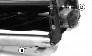
· Solid rollers: Carefully turn bottom adjusting nut (D) until the solid center piece of the roller (E) (not the end caps) just touches the gauge.
This is determined by turning the roller and listening for the scratching sound.
· Rollers with scrapers: A screwdriver can be inserted in slot in scraper, lifted up, and screwdriver handle hooked under reel housing
NOTE: Cutting units with no front roller (fixed position) set rear roller only.
12. After setting front and rear rollers on one end, lock jam nuts and recheck all gauge settings. Readjust if necessary.
13. Follow same procedure for the other end of bed knife and rollers.
14. After setting second end, go back and check first settings to be sure they haven't moved. Readjust if necessary. Gauge can snugly be placed into position on either end when properly adjusted.
Adjusting Reel-To-Bed Knife Clearance
This adjustment, combined with the backlapping operation, will ensure a clean cut as well as reduce wear, take less power, and reduce down time.
Reel-to-bed knife clearance should be checked BEFORE and AFTER backlapping.
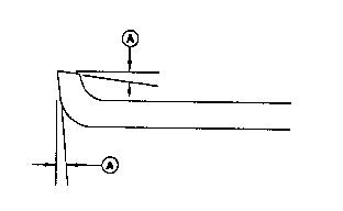
1. The cutting edge of the bed knife must be sharp and straight, and the relief angle should be 5 degrees (A) as shown.
Otherwise, remove bed knife and bed knife support and have them ground as a complete unit.
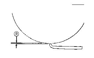
2. Use feeler gauges to set recommended reel-to-bed knife clearance (B) in the range for the grass to be cut.
Finer textured grasses, such as rye grass or bent grass requires a close setting, but the setting should not be less than 0.05 mm (0.002 in.). They also require a sharp reel and bed knife to cut properly.
3. Place a 0.05 mm (0.002 in.) feeler gauge (A) between bed knife and reel. Check at both ends of reel and two areas near the center.
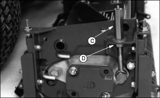
4. If adjustment is necessary, loosen jam nut (B) and adjusting nut (C) at both ends of the reel, equal amounts, preferably one flat at a time.
5. Turn adjusting nuts (C) clockwise to raise reel.
· Turn jam nut (B) clockwise to lower reel. Adjust reel until 0.05 mm (0.002 in.) is reached across the entire reel and bed knife.
6. Tighten adjusting nuts (C) and jam nuts (B). Recheck to insure reel has not moved. Readjust if necessary.
IMPORTANT: Avoid damage! DO NOT allow the reel to interfere with the bed knife. Interference will cause heating and can damage reel and bed knife. |
Backlapping Cutting Units
NOTE: Backlapping valve is optional.
IMPORTANT: Avoid damage! The reel-to-bed knife clearance should be adjusted to approximately 0.076 mm |
Backlapping cutting units must be done on a routine basis to prolong reel life, prevent downtime, and provide sharp cutting action.
1. Set Park brake and start engine.
2. Lower all cutting units to the ground.
NOTE: Cutting units are backlapped all at once.
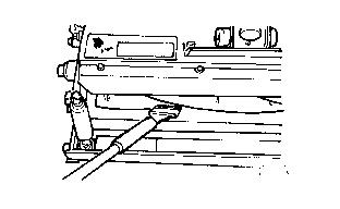
3. Lift the left access cover to expose the Backlapping valve.
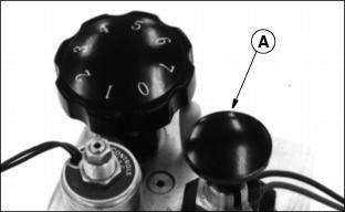
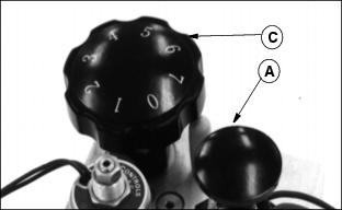
4. Position machine in backlapping mode by pulling up on the Forward/Reverse knob (A).
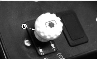
5. The PTO switch (B) can now be pulled up to ON while the operator is on or off the machine. The reels will turn backward.
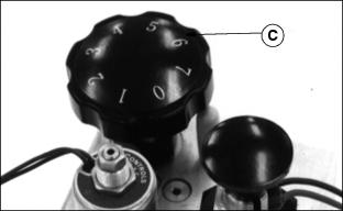
6. Rotate the flow control knob (C) to adjust the reel speed. Turn the knob clockwise to decrease the reel speed, counterclockwise to increase reel speed.
7. Adjust reel speed slowly enough so grinding compound will not be thrown off during backlapping.
8. Using a long haired brush, carefully apply reel sharpening compound, uniformly, from one end of the reel to the other. Repeat application in opposite direction. Allow unit to continue running backwards until reel is quiet.
9. Periodically disengage PTO switch and shut engine off to visually check blade appearance.
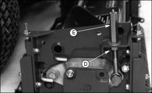
10. Adjust reel-to-bed knife clearance by loosening jam nut (D) and turning adjusting nut (E) and jam nut (D) to proper clearance on both ends.
11. Check for uniform clearance across entire bed knife. If clearance is not uniform, repeat Steps 6-10 until clearance is uniform across entire bed knife.
IMPORTANT: Avoid damage! Turn flow control knob fully counterclockwise when the backlapping operation is complete. |
12. Disengage the PTO switch and shut off the engine. Turn flow control knob (C) fully counterclockwise.
13. Push forward/reverse knob (A) down to resume normal operation.
IMPORTANT: Avoid damage! Do not operate units in the forward direction until reel sharpening compound is washed from the unit. Unless properly washed, the reels can be dulled by the compound. |
14. With reel stopped, use water to thoroughly wash off all reel sharpening compound.
Readjust Reel-To-Bed Knife Clearance
See Adjusting Reel-To-Bed Knife Clearance in this section.
Grinding The Bed Knife
NOTE: Bed knife removed for illustration purposes only.
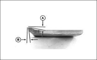
When grinding the bed knife, it is important to have a 5 degree relief angle on top surface (A) and front surface (B).
Replacing Bed Knife
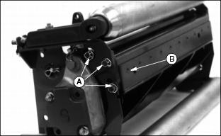
1. Remove six cap screws (A) attaching bed knife support to cutting unit housing, (three on each end).
2. Remove bed knife support, with bed knife attached from cutting unit housing.
3. Remove and discard screws and nuts attaching bed knife to support. Discard bed knife.
4. Remove debris, corrosion, and rust from bottom surface of bed knife support.
5. Install end screws (B), tighten to secure knife to support, to properly position knife.
6. Install rest of screws and nuts.
7. Torque nuts to 1/2 torque, approximately 26 N·m (19 lb-ft), starting from the center and work out towards the ends.
8. Finish torquing to full torque, 51 N· m (38 lb-ft), starting from the center and work out towards the ends. Minimum torque is 45 N·m (33 lb-ft).
9. Put bed knife support and bed knife in a suitable grinder and grind until knife is flat and uniformly ground across the top surface.
10. Raise reel by turning the reel adjusting nut (C) clockwise and nut (D) counterclockwise until the knife and support can be installed.
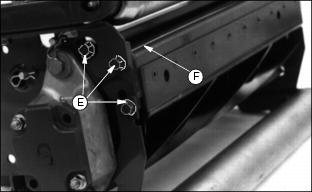
11. Reinstall the bed knife support assembly and snug cap screws (E) on both ends.
12. Tap both ends of bed knife (F) away from reel with a brass hammer to remove any play in bed knife support. Tighten cap screws to 43 N·m (32 lb-ft).
13. Set the height-of-cut. (See Adjusting Height-Of-Cut in this section.)
14. Adjust the reel-to-bed knife. (See Adjusting Reel-To-Bed knife in this section.)
15. Backlap reel. (See Backlapping Cutting Units in this section.)
16. Check the height-of-cut and adjust as necessary. (See Adjusting Height-Of-Cut in this section.)