![]()
3215B TURF SYSTEM I PIN (030001-)
3225B TURF SYSTEM II PIN (020001-)
3235B TURF SYSTEM II PIN (030001-)
Introduction
Product Identification
Safety
Operating Machine
Operating Cutting Units
Replacement Parts
Service Intervals
Service Lubrication
Service Engine
Service Transmission
Service Cutting Units
Avoid Injury From Contacting Blades
Rotate For Service (RFS) Cutting Units (22 ESP only)
Adjusting Cutting Units (22 ESP)
Preparing Cutting Units For Mowing (After RFS Servicing - 22 ESP only)
Removing Cutting Units (22 ESP)
Removing and Installing Front Roller (2500M)
Removing and Installing Rear Roller (2500M)
Removing and Installing Bed Knife (22 ESP)
Cleaning Roller Scraper (22 ESP)
Installing Reel Adjustment Washers
Service Electrical
Service Miscellaneous
Troubleshooting
Storage
Assembly
Specifications
Warranty
John Deere Quality Statement
Service Record
Copyright© Deere & Company

Service Cutting Units
Avoid Injury From Contacting Blades
Grease
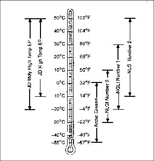
Use grease based on the expected air temperature range during the service interval.
The following grease is preferred:
· John Deere HIGH TEMPERATURE EP GREASE
Other greases may be used if they meet one of the following:
· SAE Polyurea Grease - NLGI Grade 0.
· SAE Calcium Complex Grease - NLGI Grade 0.
Greases meeting Military Specification MIL-G-10924F may be used as arctic grease.
Rotate For Service (RFS) Cutting Units (22 ESP only)
ESP cutting units feature the RFS-Rotate For Service-suspension system for ease of access for service.
2. Lock park brake and shut off engine.

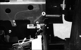
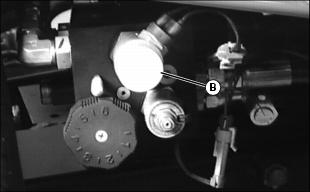
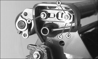
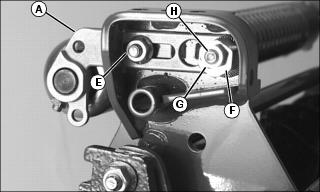
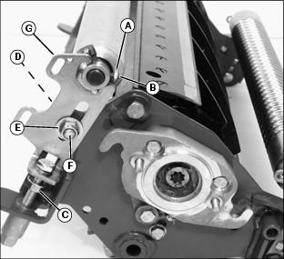
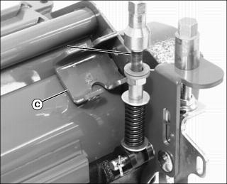
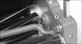
3. Push down on the spring (A) for front cutting units.
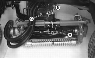
4. Push down on the spring (A) for rear cutting units. Remove retaining pin (B) and insert with the short leg in the hole and the long leg in the channel (C) on the arm. Turn the cutting units outward.

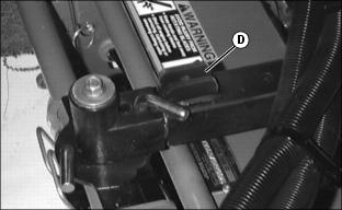
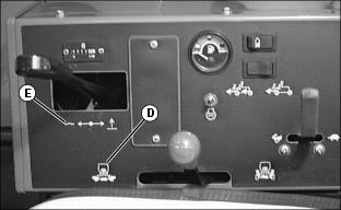
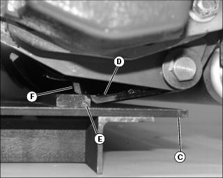
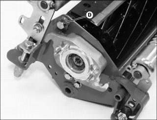
5. At right rear above rear cutting unit, rotate the rear lift arm stop (D) into the locked position as shown.
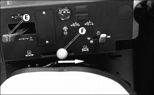
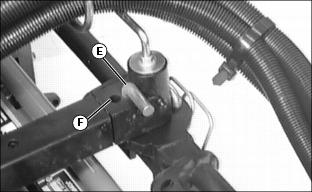
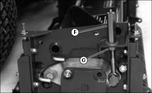
6. Pull Mow/Transport lever (F) back to transport position, start the engine from the seat.
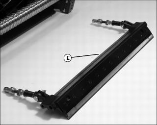
7. Move the Mow/Transport lever (F) forward into mow and pull back the Lift/Lower lever (E) to raise the cutting units to the mow lift height.
NOTE: All cutting units should be pointing up because the retaining pins are not in place.
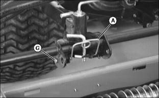
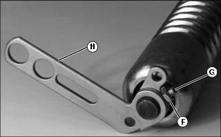
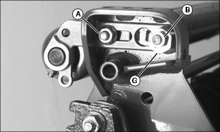
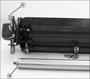
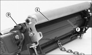
9. Pull the spring lever (A) back up to the normal position. Then, pull the cutting unit up by the front roller so the pins align with the rear service lock hole (G) and lock into the service position. Lock the rear cutting units in place facing the outside.
10. Move the Mow/Transport lever back to the transport position.
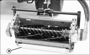
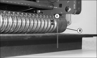
12. Lower the cutting units so the rear roller (H) is on the floor. This stabilizes the cutting units and takes the load off the lock pins.
13. Stop the engine. The cutting units are now ready for servicing.
Adjusting Cutting Units (22 ESP)
NOTE: Adjustments may affect each other. It is important that adjustments be made in the following sequence.
1. Adjust the reel-to-bed knife clearance.
2. Set units for the height-of-cut.
3. Perform the backlapping operation.
4. Check reel-to-bed knife clearance and adjust if necessary.
Preparing Cutting Units For Mowing (After RFS Servicing - 22 ESP only)

1. Release the spring levers (A) on all five cutting units, when finished servicing.
2. Start the machine and pull the lift lever back to raise the cutting units, causing them to hang in their normal free positions.
3. Push the lift lever forward to lower them back down.
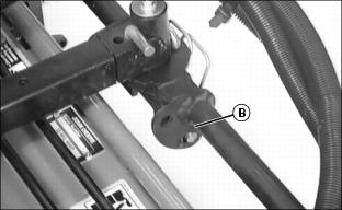
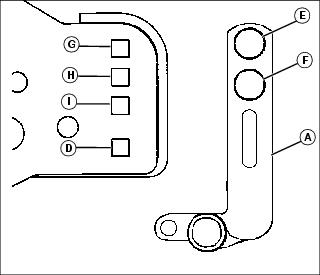
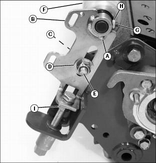
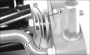
4. Shut off the engine and put the spring levers back up on each cutting unit. Jiggle them to make sure the pins lock into the front normal operating position (B).
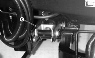
5. Turn the rear cutting units to face forward again. Rotate the rear lift arm stop (C) back into the unlocked position.
6. Install the retaining pins for the rear cutting units with the short leg of the pin not sitting in the channel (D).
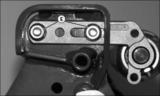
7. The RFS system allows a choice of Fixed Steer and Normal Steer cutting unit mowing options.
· Fixed Steer--insert longer leg of pin into the front hole (E) as shown.
· Normal Steer--insert pin into the rear hole (F).
Removing Cutting Units (22 ESP)
1. Park machine safely. (See Park Safely in the SAFETY section.)
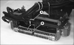
2. Push spring (B) down and remove front pin (A).
3. Remove hoses from hose supports.
4. Pull unit away from the mower.
5. Refer to technical manual to remove reel motor.
Backlapping Cutting Units
NOTE: Reel-to-bed knife clearance should be checked before and after backlapping.
1. Lower the cutting units to the ground. The cutting units should be in the Rotate For Service position (22 ESP) or in the mowing position.
NOTE: Service switch is located under the seat platform.
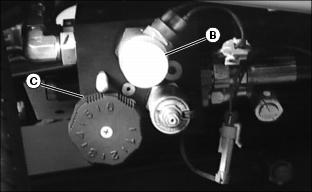
2. Lock park brake and set the service switch (A).
NOTE: Multiple cutting units are backlapped at the same time.
3. Start the engine, and set the throttle on low idle.
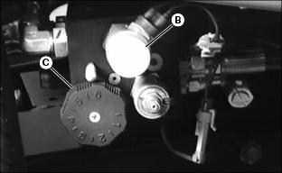
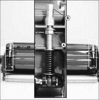
4. Pull Forward/Reverse knob (B) out for each backlapping valve.
5. Turn both speed control knobs (C) clockwise to (1) on knob.
6. Put Mow/Transport lever in mow (D). Push the Lift/Lower lever forward to lower position (E).
· Cutting units will begin rotating in reverse for backlapping.
7. Slowly rotate the speed control knob (C) counterclockwise to adjust the reel speed. Adjust reel speed so backlapping compound will not be thrown off during backlapping.
8. Use a long handled brush to carefully apply reel sharpening compound uniformly, from one end of the reel to the other. Repeat application in opposite direction. Allow unit to continue running backwards until reel is quiet.
9. Periodically disengage cutting units by pushing the Forward/ Reverse knob (B) in and shutting engine off to visually check blade appearance.
10. Adjust reel-to-bed knife clearance by loosening jam nut (G) and turning adjusting nut (F) and jam nut (G) to proper clearance on both ends. Check for uniform clearance across entire bed knife. If clearance is not uniform, repeat steps 6 through 10 until clearance is uniform across entire bed knife.
IMPORTANT: Avoid damage! Do not operate units in the forward direction until reel sharpening compound is washed from the unit. Unless properly washed, the reels can be dulled by the compound. |
11. Use low pressure water to thoroughly wash off all reel sharpening compound while reels are turning in reverse.
12. Push Forward/Reverse knobs (B) in.
IMPORTANT: Avoid damage! Both reel speed control knobs must be set at the same speed when backlapping procedure is completed. |
13. Shut off engine. Turn reel speed control knobs (C) fully counterclockwise to (6) on the knob. Return the service switch back to mow position and lower seat.
Grinding the Bed Knife
NOTE: If cutting edge needs grinding, remove bed knife and bed knife support together and have them ground as a complete unit.
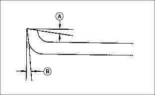
NOTE: It is recommended to have a 6 degree relief angle on top surface (A) and a 5 degree relief on the front surface (B).
Removing and Installing Front Roller (2500M)
1. Remove cutting unit from Lightweight Fairway mower.
2. Position cutting unit upright on a flat surface or workbench.
3. Loosen and remove hardware from left roller bracket.
· Remove flange nut (A) and carriage bolt from lower hole.
· Remove lock nut (B), eccentric adjuster (C), serrated washer (D) and carriage bolt.
4. Loosen and remove hardware from right roller bracket.
· Remove flange nuts (E) and carriage bolts.
5. Remove roller and bracket assembly from cutting unit frame.
Picture Note: Photo shows left roller bracket being removed.
· Loosen jam nut (F) and set screw (G).
· Remove bracket (H) from each bearing spindle shaft end.
Installing Front Roller
NOTE: Roller brackets are offset. For standard use, the bracket should be installed to the roller with the offset to the rear of the base cutting unit to allow close proximity of front roller to rear roller.
Install the roller bracket with the larger holes and adjustment slot on the left side of the cutting unit, in the direction of travel.
The roller bearing spindle shaft has holes drilled in each end. Do not tighten set screws near the holes.

Picture Note: Photo shows left roller bracket being installed.
1. Install roller brackets (A) onto each bearing spindle shaft end.
· Install set screws (B) and lock nuts (C) loosely. Do not tighten.
2. Select Height of Cut (HOC) adjustment range.
· Alignment of roller bracket (A) and cutting unit frame (D) adjustment holes will determine HOC adjustment range.
· Refer to chart for desired setting.
3. Install front roller and roller bracket assembly.
· Slide assembly roller brackets (A) into cutting unit frame slots.
· Align selected HOC adjustment holes.
NOTE: Install carriage bolts from the inside.
· Fasten bottom of left roller bracket to frame using one M8x20 carriage bolt and one M8 flange nut (E).
NOTE: Install serrated washer with cupped side facing cutting unit frame.
· Fasten top of left roller bracket to frame using one M8 x 40 carriage bolt, one serrated washer (F), one eccentric adjuster (G) and one M8 lock nut (H).
· Fasten right roller bracket to frame using two M8 x 20 carriage bolts and two M8 flange nuts (I).
· Tighten roller bracket attaching hardware.
NOTE: Make sure the roller bracket set screw locations are not aligned with the holes in each bearing spindle shaft end. Set screws must engage the bearing spindle shaft at each end.

· Center front roller. Tighten set screws (B) and jam nuts (C) on both roller brackets.
Parallelism Adjustment with Bench Plate
1. Position cutting unit upright on flat surface or workbench.

2. Loosen hex nut (A) and hex nut (B) on the left roller bracket.
3. Set bench plate on a level surface. Set cutting unit on top of bench plate (C). Bed knife (D) must rest firmly against plate stop (E) with cutting reel blade (F) on top of plate stop.
4. Rotate eccentric adjuster (G) until the front roller (H) sits flat and parallel with the bench plate. Gap (I) should not exceed 0.050 mm (0.002 in.) maximum.
5. Tighten left roller bracket hex nut (A).
6. Tighten left roller bracket hex lock nut (B).
Removing and Installing Rear Roller (2500M)
Removing Rear Roller
1. Remove cutting unit from machine.
2. Position cutting unit on a flat surface or workbench.
3. On each side of rear roller, loosen jam nut (A) and set screw (B).
4. Loosen jam nut (C) on each adjuster tower.
5. Remove carriage bolt (D), flat washer (E) and lock nut (F) attaching each height-of-cut (HOC) adjustment bracket (G) to the cutting unit frame.
6. Move height of cut (HOC) brackets (G) away from each bearing spindle shaft end.
Installing Rear Roller
1. Install roller bearing spindle shafts (A) into each height-of-cut (HOC) bracket (B).
2. Attach both height of cut brackets to cutting unit frame.
NOTE: Install carriage bolts from the inside.
· Install carriage bolt (C), flat washer (D) and lock nut (E).
3. Center rear roller (F) inside HOC brackets.
4. Tighten set screws (G) and jam nuts (H).
5. Loosen lock nuts (E) approximately 1/4 turn.
6. Tighten jam nut (I) on each adjuster tower.
Replacing Bed Knife (2500M)
Removing Bed Knife
1. Remove cutting unit from machine.
2. Position cutting unit on a flat surface or workbench.
3. Relieve tension from bed knife tension springs on both sides of cutting unit.
· Turn jam nuts (A) counterclockwise until springs are completely compressed.
5. Rotate each adjustment assembly away from reel housing bracket (C).
6. Position cutting unit on flat surface or workbench as shown.
7. Remove shoulder bolt (D) from each end of cutting unit.
8. Slide bed knife assembly (E) out of the cutting unit housing.
NOTE: Remove debris, corrosion, and rust from bottom surface of bed knife support.
· Remove and discard thirteen screws attaching bed knife to assembly support. Discard bed knife.
· Install bed knife using new screws. Alternate tightening by starting with center screws.
10. Put bed knife support and bed knife in a suitable grinder and grind until material is removed from the entire top surface of the bed knife lip.
Installing Bed Knife
1. Slide bed knife and support assembly (E) into position inside locator shoe (F).
2. Install both shoulder bolts (D).
· Tighten hardware to 55 N·m (40 lb-ft).
3. Position cutting unit on flat surface or workbench.
4. Install each adjustment assembly inside housing mounting bracket.
· Restore bed knife spring tension by turning jam nuts (A) clockwise. Turn jam nut bushings only midway up the threaded adjustment.
8. Check height of cut and adjust as necessary.
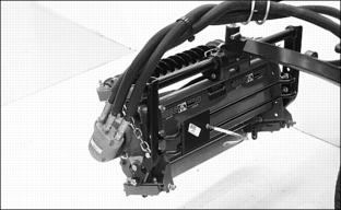
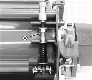
Removing and Installing Bed Knife (22 ESP)

1. Remove 6 cap screws (A) attaching bed knife support to cutting unit housing (3 on each end).
2. Remove bed knife support, with bed knife attached from cutting unit housing. Remove and discard screws (B) and nuts attaching bed knife to support. Discard bed knife.
3. Remove debris, corrosion, and rust from bottom surface of bed knife support.
4. Install the outer screws and nuts loosely to position the bed knife. Starting with the center mounting hardware and working towards the ends of the bed knife and alternating from side to side, torque hardware in two steps to a final torque of 51 N·m (38 lb-ft.).
5. Place bed knife support and bed knife in a suitable grinder and grind until knife is flat and uniformly ground across the top surface.
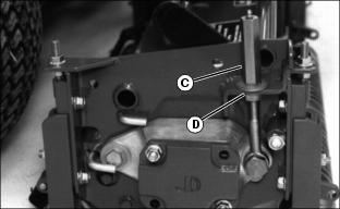
6. Raise reel, by turning the reel adjusting nut (C) clockwise and nut (D) counterclockwise, until the knife and support can be installed.
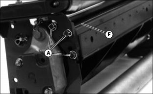
7. Install the bed knife support assembly, and snug cap screws (A) on both ends.
8. Tap both ends of bed knife (E) with a brass hammer to remove any play in bed knife support. Tighten cap screws to 63 N·m (46 lb-ft).
9. Adjust the reel-to-bed knife clearance.
12. Check the reel-to-bed knife clearance and adjust as necessary.
Cleaning Roller Scraper (22 ESP)
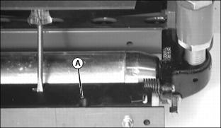
1. Place screwdriver in either slot (A) in scraper and push towards reels. Scraper will lift for easier cleaning.
Installing Reel Adjustment Washers
NOTE: It is NOT necessary to remove reel adjustment hardware (A) to adjust reel to bed knife clearance.
1. Install flat pivot washer (B) onto bolt.
2. Install one spring washer (C) onto bolt with cupped side toward flat washer.
3. Install second spring washer (D) with cupped side out and install last spring washer (E) with cupped side in. The cupped sides of D and E should face each other.