![]()
3215B TURF SYSTEM I PIN (030001-)
3225B TURF SYSTEM II PIN (020001-)
3235B TURF SYSTEM II PIN (030001-)
Introduction
Product Identification
Safety
Operating Machine
Operating Cutting Units
Replacement Parts
Service Intervals
Service Lubrication
Service Engine
Service Transmission
Service Cutting Units
Service Electrical
Checking Battery Electrolyte Level
Replacing Indicator Light Bulbs
Electrical Components (Rear Section)
Electrical Components (Front Section)
Service Miscellaneous
Troubleshooting
Storage
Assembly
Specifications
Warranty
John Deere Quality Statement
Service Record
Copyright© Deere & Company

Service Electrical
Battery Statement
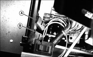
Cleaning or Replacing Battery
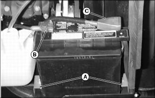
1. Remove two 10 mm bolts and clips (A) securing battery to frame.
2. Remove negative (black) cable (B) from battery first.
3. Remove positive (red) cable (C).
4. Remove battery, If battery is very dirty.
5. Clean battery, battery terminals, cable ends and battery ledge with a solution of 1 part baking soda to 4 parts water. keep solution out of battery cells.
6. Rinse all parts with clean water. Let it dry.
7. Install battery. Connect negative cable last.
Checking Battery Electrolyte Level
NOTE: Add only distilled water to replace normal electrolyte loss.
IMPORTANT: Avoid damage! Do not fill cells to the bottom of the filler neck (B). Electrolyte can overflow when battery is charged and cause damage. |
1. Remove battery manifold cap to check electrolyte level.
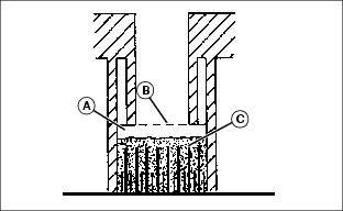
2. Electrolyte level (A) should be 6 mm. (1/4 in) above plates (C).
3. Add distilled water if necessary.
4. Install manifold cap. Be sure manifold cap hose is installed behind positive (+) cable.
Using Booster Battery
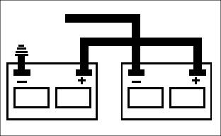
1. Connect positive (+) booster cable to booster battery (A) positive (+) post (C).
2. Connect the other end of positive (+) booster cable to the disabled vehicle battery (B) positive (+) post (D).
3. Connect negative (-) booster cable to booster battery negative (-) post (E).
4. Connect the other end (F) of negative (-) booster cable to a metal part of the disabled machine frame away from battery.
5. Start the engine of the disabled machine and run machine for several minutes.
6. Carefully disconnect the booster cables in the exact reverse order: negative cable first and then the positive cable.
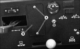
Replacing Fuses
NOTE: Fuse holders are located under seat by the service switch.
· (A)10 amp fuse--switched power (has yellow/black wire and yellow/white wire leads).
· (B) 20 amp fuse--lights and auxiliary power (has yellow/black wire and yellow red wire leads).
1. Pull back tab to slide fuse case apart and replace defective fuse.
2. Replace with fuse of correct amperage.
Replacing Indicator Light Bulbs
2. Pull indicator light module (B) up and out.

3. Twist bulb socket (C) counterclockwise 1/4 turn and pull out.
4. Pull bulb (D), carefully, straight out of socket and replace with a new bulb.
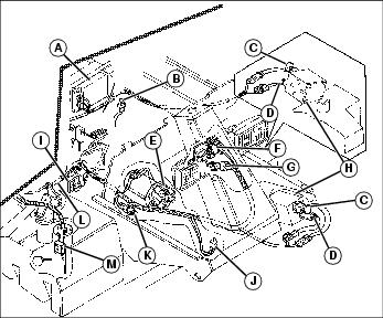
Electrical Components (Rear Section)
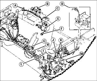
C - Protection Diode (Fuel Shut-off)
D - Transmission Neutral Switch (3235B looks different)