![]()
3215B TURF SYSTEM I PIN (030001-)
3225B TURF SYSTEM II PIN (020001-)
3235B TURF SYSTEM II PIN (030001-)
Introduction
Product Identification
Safety
Operating Machine
Avoid Damage To Plastic And Painted Surfaces
Adjusting Mow Speed (3215B/3225B)
Adjusting Mow and Transport Speeds (3235B)
Testing Mow/Transport Lever Switch
Using Engine Cold Start Switch
Using Four Wheel Drive Traction Unit (Optional)
Using Hydrostatic Transmission
Operating Cutting Units
Replacement Parts
Service Intervals
Service Lubrication
Service Engine
Service Transmission
Service Cutting Units
Service Electrical
Service Miscellaneous
Troubleshooting
Storage
Assembly
Specifications
Warranty
John Deere Quality Statement
Service Record
Copyright© Deere & Company

Operating Machine
DAILY OPERATING CHECKLIST
o Remove grass and debris from machine.
o Remove grass and debris from engine compartment and muffler area, before and after operating machine.
o Check around hose fittings for leaks.
o Check Air Restriction Indicator.
o Check reels and bed knives for sharpness and nicks.
o Check reel-to-bedknife settings (22 ESP).
o Check bedknife-to-reel settings (2500M).
o Grease front and rear rollers.
o Grease RFS springs (22 ESP).
Avoid Damage To Plastic And Painted Surfaces
· Insect repellent spray may damage plastic and painted surfaces. Do not spray insect repellent near machine.
· Be careful not to spill fuel on machine. Fuel may damage surface. Wipe up spilled fuel immediately.
Dash Controls
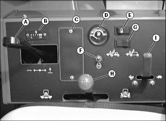
G - Power Assist Switch (Optional)
Foot Controls
Steering Column Control

Miscellaneous Controls
Picture Note: Reel knobs are located under the foot platform and under the left fender.
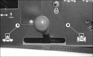
Picture Note: Under seat-3215B and 3225B
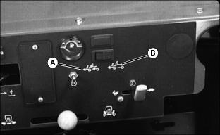
Picture Note: Under seat-3235B
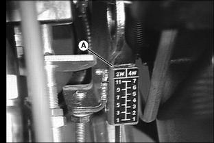
A - Mow Speed Adjustment (3215B/3225B))
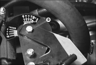
B - Mow/Transport Speed Adjustment 3235B
Indicator Lights
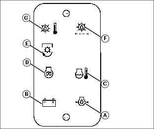
A - Engine Oil Pressure Indicator
B - Battery Discharge Indicator
C - Engine Coolant Temperature Indicator
D - Engine Cold Start Indicator
F - High Hydraulic Oil Filter Pressure Indicator
G - High Hydraulic Oil Temperature Indicator
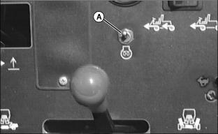
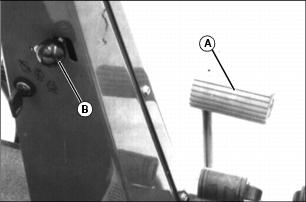
Adjusting Mow Speed (3215B/3225B)
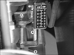
1. Loosen nut (A) and turn bolt (B), so that the mark (C) aligns with a corresponding number for desired maximum mow speed.
2. Tighten nut (A) when desired maximum mow speed is selected.
Adjusting Mow and Transport Speeds (3235B)
IMPORTANT: Avoid damage! Moving one adjusting arm may move the other arm. Check both speed selections before tightening hardware. |

· Loosen two bolts (C) and align bottom arm (A) with corresponding number for desired maximum speed.
· Tighten bolts when desired maximum speed is selected.
2. Select maximum transport speed:
· Loosen two bolts (C) and align top arm (B) with corresponding number for desired maximum speed.
· Tighten bolts when desired maximum speed is selected.
Testing Safety Systems
Use the following checkout procedure to check for normal operation of mower.
If there is a malfunction during one of these procedures, Do not operate mower. See your John Deere dealer for service.
Perform these tests in a clear open area. Keep bystanders away.
Testing Mow/Transport Lever Switch
2. Depress brake pedal, or lock park brake.
3. Put Mow/Transport lever in mow position.
4. Turn key to start position.
Testing Seat Switch
Test 1:
3. Unlock park brake and release brake pedal.
4. Put Mow/Transport lever in MOW position.
5. Raise up off seat. do not get off machine.
Test 2:
1. Move Mow/Transport lever to transport.
4. Raise up off seat. Do not get off machine.
· Move Mow/Transport lever to transport.
· Raise up off seat. do not get off machine.
· Engine should continue to run.
Test 3:
1. Move Mow/Transport lever to transport.
4. Raise up off seat. do not get off machine.
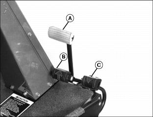
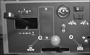
Using Mow/Transport Lever
1. Move lever forward to mow position (A) to allow cutting units to be engaged when Lift/Lower lever is pushed forward.
2. Move lever rearward to transport position (B) to disengage reel drive for cutting units.
Using Lift/Lower Lever
NOTE: Rear cutting units are time-delayed to lower to ground and raise after front cutting units.
With Mow/Transport lever forward in mow position:

· Move lever forward (A) to lower cutting units to begin mowing operation.
· Move lever rearward (B) to lift cutting units while turning during cutting operation.
With Mow/Transport lever in transport position:
· Move Lift/Lower lever rearward (B) to raise cutting units for transport.
Using Engine Cold Start Switch
NOTE: If air temperature is 4°C (40°F) or colder, it may be necessary to warm engine intake air to assist in engine starting.
1. Activate air heater by holding cold start switch (A) down for 20 to 30 seconds.
Using Four Wheel Drive Traction Unit (Optional)
NOTE: Ground speed will decrease when 4WD is turned on.
The four-wheel drive system is automatically turned on with the Mow/Transport lever in mow position. Four-wheel drive is not activated in reverse in either mow or transport position. Moving the lever to the transport position will disengage the 4WD. It can be turned on in transport position using rocker switch.
1. Push rocker switch forward (A) to turn 4WD ON.
2. Push rocker switch rearward (B) to turn 4WD OFF.
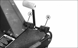
Using Park Brake
NOTE: The park brake can be used to stop the machine in an emergency. Reels cannot engage with park brake pedal depressed.
To lock the park brake:
· Move knob (B) to the bottom of the slot.
· Push pedal (A) down. Pedal will stay down.
To unlock the park brake:
· Push and hold pedal (A) down.
· Move knob (B) to the top of the slot.
Indicator Lights
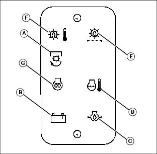
· The "Reel Engaged" indicator (A) will come on when the Mow/Transport lever is moved into the mow position.
· "Battery Discharge" indicator (B) will come on when key is first turned on to on and should go out when engine starts. If indicator comes on while operating machine, perform appropriate service.
NOTE: C, D, E and F have audible alarm.
· "Low Oil Pressure" indicator (C) will come on when key is first turned on to ON and should go out when engine starts.If light remains on or comes on while operating machine, stop engine immediately and perform appropriate service.
· "High Engine Temperature" indicator (D), indicates excessive engine heat. Pull over to side of fairway and let engine idle for several minutes to cool down. Perform necessary service to machine before operating.
· "High Hydraulic Oil Filter Pressure" indicator (E), indicates above-normal pressure across the hydraulic filter. Replace filter.
· "High Hydraulic Oil Temperature" light (F) indicates hydraulic oil is over-heating. Pull over to side of fairway and let engine idle for several minutes to cool down. Perform necessary service to machine before operating.
· "Engine Cold Start" indicator (G) will come on when the cold start switch is used in cold weather and will go out when operator releases switch.
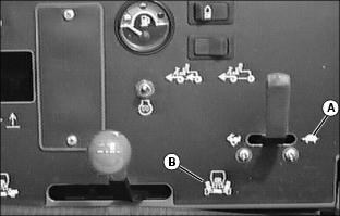
Safety Interlock System
For the starter to engage and the engine to run, the following conditions must be met simultaneously:
· Mow/Transport lever must be in the transport position (A). Hydrostatic drive pedals should be in neutral.
· Operator should be in seat and/or park brake locked.
· If the operator is mowing (Mow/Transport lever forward to mow (B)) and the operator leaves the seat, the engine will stop.
· If the operator has stopped mowing, and moves Mow/Transport lever back to transport position and leaves the seat with ground drive in neutral, but without the park brake locked, the engine will stop.
· If the operator attempts to drive forward or backward while the park brake is locked, the engine will Stop.
· If Mow/Transport is in mow, depressing park brake will shut reels off. Reels will not rotate with the park brake depressed.
NOTE: Provision has been made to allow a trained operator to backlap the reels from the ground with the engine running and the cutting units in motion. (See SERVICE-CUTTING UNITS section for procedure.)
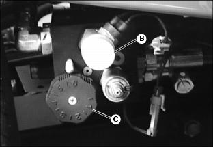
Starting The Engine
2. Put all operating controls in neutral.
3. Move Mow/Transport lever to transport position.
4. Set throttle to 1/4 throttle.
· Battery Discharge and Low Oil Pressure indicator lights must light.
6. Hold the cold start switch (B) in position for 20 - 30 seconds, if air temperature is 4°C (40°F) or colder, the air heater should be activated.
7. Turn key to start to start engine.
· All indicator lights should light and then go out.
8. Release key to the on position when the engine starts.
· All indicator lights should go out.
· If any stay on, stop the engine immediately. Diagnose and correct the problem before starting engine.
9. Check that Safety interlock system steps are being followed, if engine does not start.
Stopping Engine
1. Move throttle lever down to slow idle position (A). Let engine idle momentarily before stopping.
2. Move Mow/Transport lever to transport position (B) and lower cutting units.
Using Hydrostatic Transmission
NOTE: Removing foot from FORWARD or REVERSE control pedal will act as a brake for the machine. Top mowing speed for all models and transport speed for the 3235B can be regulated by the Mow Speed Adjustment.
2. Move throttle lever all the way forward to high idle position.
3. To travel forward, slowly push hydrostatic control Forward pedal (A) down. The farther the pedal is pushed down, the faster the mower will travel.
· Mowing -- 0-11.2 km/h (0-7 mph)
· Transport -- 0-17.7 km/h (0-11 mph)
· Mowing -- 0-12 km/h (0-7.5 mph)
· Transport -- 0-20 km/h (0-12.5 mph)
4. To travel in reverse, slowly push reverse pedal (B) down. The farther the pedal is pushed down the faster the mower will travel.
· Reverse travel speed is 0-8.8 km/h (0-5.5 mph).
Transporting Mower On Trailer
IMPORTANT: Avoid damage! To prevent damage to transmission: · Do not pull or push the mower over a long distance. · Transport mower on a trailer. |
NOTE: Trailer must have signs and lights required by local, state, provincial, or federal laws.
1. Drive the mower forward onto the trailer.
IMPORTANT: Avoid damage! All cutting units must be lowered onto the trailer to prevent damage to the mower. |
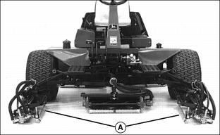
3. Pull pin and release spring to detach the two front outside cutting units from the mower. Place cutting units in position (A) and strap securely to the trailer.
4. Use welded loops and holes in the frame that is conveniently located as anchoring locations for chains, cables or straps.
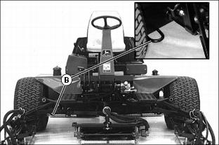
· There are two front welded loops (B),
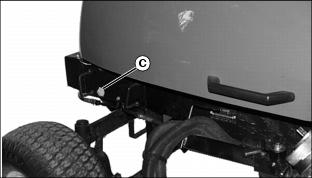
· One rear hole (C) on either side provides for anchoring.
5. Install the straps, chains, or cables through these holes and secure to the trailer.
6. Securely latch the mower hood.
Driving Mower To Work Site
NOTE: When driving mower a long distance, use lift locks to support front cutting units.
1. Raise front cutting units completely.
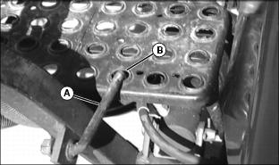
2. Engage lock arm (A) into footrest hole (B) on each side.
Pushing Fairway Mower
IMPORTANT: Avoid damage! Do not tow Fairway Mower behind another vehicle. Do not push a long distance. Transport mower on a trailer. |
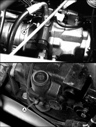
Picture Note: Top photo shows transmission unlock pin (A) on Model 3215B/3225B. Bottom photo shows Model 3235B.
To move the mower when engine is not running:
1. Raise operator seat to service position.
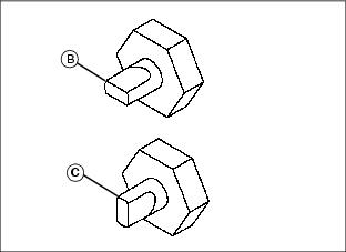
2. Turn pin to horizontal position (B) to disconnect transmission.
4. Push or pull mower to desired location.
5. Turn pin to vertical position (C) before starting engine.