![]()
3215B TURF SYSTEM I PIN (030001-)
3225B TURF SYSTEM II PIN (020001-)
3235B TURF SYSTEM II PIN (030001-)
Introduction
Product Identification
Safety
Operating Machine
Operating Cutting Units
Replacement Parts
Service Intervals
Service Lubrication
Service Engine
Service Transmission
Service Cutting Units
Service Electrical
Service Miscellaneous
Troubleshooting
Storage
Assembly
Installing Front Roller (2500M)
Install Grasscatchers (22 ESP)
Install Scraper Blade (22 ESP)
Specifications
Warranty
John Deere Quality Statement
Service Record
Copyright© Deere & Company

Assembly
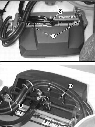
Charge Battery

Charge the battery for a minimum of 30 minutes at 5-10 amps. If your battery charger has a Deep Cycle or Maintenance Free setting, use this setting to charge the battery. Failure to charge the battery before use will reduce battery performance and life.
Installing Front Roller (2500M)
NOTE: Roller brackets are offset. For standard use, the bracket should be installed to the roller with the offset to the rear of the base cutting unit to allow close proximity of front roller to rear roller.
Install the roller bracket with the larger holes and adjustment slot on the left side of the cutting unit, in the direction of travel.
The roller bearing spindle shaft has holes drilled in each end. Do not tighten set screws near the holes.
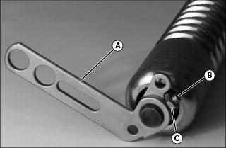
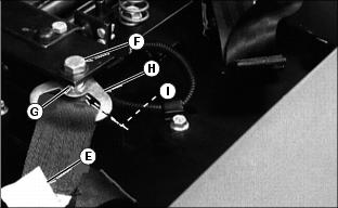
Picture Note: Photo shows left roller bracket being installed.
1. Install roller brackets (A) onto each bearing spindle shaft end.
· Install set screws (B) and lock nuts (C) loosely. DO NOT tighten.
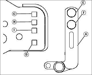
2. Select Height of Cut (HOC) adjustment range.
· Alignment of roller bracket (A) and cutting unit frame (D) adjustment holes will determine HOC adjustment range.
· Refer to chart for desired setting.
3. Install front roller and roller bracket assembly.
· Slide assembly roller brackets (A) into cutting unit frame slots.
· Align selected HOC adjustment holes.
NOTE: Install carriage bolts from the inside.
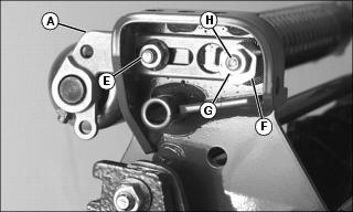
· Fasten bottom of left roller bracket to frame using one M8 x 20 carriage bolt and one M8 flange nut (E).
NOTE: Install serrated washer with cupped side facing cutting unit frame.
· Fasten top of left roller bracket to frame using one M8 x 40 carriage bolt, one serrated washer (F), one eccentric adjuster (G) and one M8 lock nut (H).
· Fasten right roller bracket to frame using two M8 x 20 carriage bolts and two M8 flange nuts (I).
· Tighten roller bracket attaching hardware.
NOTE: Make sure the roller bracket set screw locations are not aligned with the holes in each bearing spindle shaft end. Set screws must engage the bearing spindle shaft at each end.
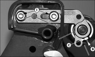
· Center front roller. Tighten set screws (B) and jam nuts (C) on both roller brackets.
Install Front Roller (22 ESP)
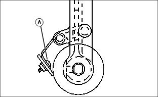
1. Remove cap plugs from ends of roller shaft.
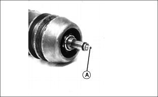
2. Insert grease fittings (A) in both ends.
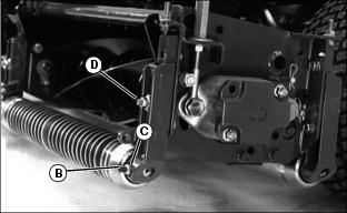
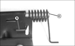
3. Thread set screw (B) half way into adjuster.
4. Thread jam nut (C) onto set screw.
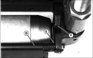
NOTE: It may be necessary to loosen the height adjuster towers (D) in order to insert the roller.
5. Install and center roller between right and left height adjusters.
Install Counterweights
Install The Cutting Units
IMPORTANT: Avoid damage! Install rollers and set units to the desired height of cut (HOC) before installing cutting units. |


2. Install coupling (K) on reel shaft and install motor.
3. Repeat steps 1 through 4 on the other cutting units.
Install Grasscatchers (22 ESP)
1. Attach the metal brace (A) with hex flange head nuts to the cutting unit yoke at (B).
NOTE: The Grasscatcher has two designs, the squared (full) basket used on the three front cutting units and the notched basket used on the back two cutting units.
Picture Note: Rear basket shown in top photo; front basket shown in bottom photo.
2. To place the basket on the yoke pull back the catcher lock (C) and place the hooked ends (D) of the basket over the top of the yokes.
Install Scraper Blade (22 ESP)
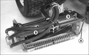
1. Fasten scraper blade to roller scraper with 3 M6 x 16 pan screws and nuts. Screw heads (A) must be installed to the inside of the scraper.
NOTE: There is a right and left hand spring and each spring has a long and short leg.
2. Insert short leg (B) of springs through slots in both ends of scraper.
3. Slide rod (C) through scraper and springs.
4. Place long leg of spring in groove (F) of height adjuster. Press down and push rod (D) into hole (E) of height adjuster.
5. Follow same procedure for other end of scraper.
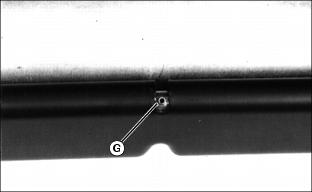
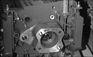
6. Align hole in rod with slot in center of scraper and drive roll pin (G) in flush with top of scraper.
Install Optional ROPS
NOTE: If Light Weight Mower is to be used for low clearance operation and ROPS is not installed, remove seat belt from the seat base.
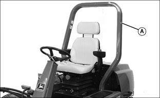
1. Install ROPS (A) angle toward rear of tractor.
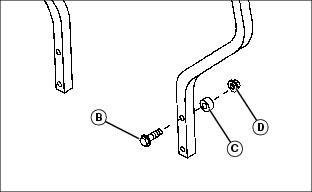
2. Put four flange head cap screws (B) through holes in ROPS.
3. Install spacers (C) and lock nuts (D) (bolt head to the front and spacers to the rear).
4. Tighten bolts to 136 N·m (100 lb-ft.).
Install Seat Belt
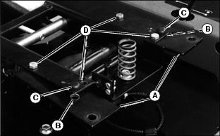
1. Install belt mounting brackets (A) by putting hole (B) over bottom tab of rubber bumper (C).
2. Fasten brackets to suspension using four M8x16 bolts and nuts (D).
NOTE: Install belt halves so white tags (E) face up.
4. Install belt halves to brackets by putting M10x30 bolts (F) in rear holes.
5. Install spacers (G) on bolts.
6. Install belt brackets (H) over spacers.
Adjusting Tire Pressure
NOTE: Tire pressure at shipment is 104 kPa (15 psi).
1. Adjust tire pressure to 83 kPa (12 psi) for best results in average use.
IMPORTANT: Avoid damage! Tire pressure should never be less than 62 kPa (9 psi) or greater than 104 kPa (15 psi). Tire pressure should be equal for all tires on mower. |
A lower pressure may improve traction and performance depending on turf conditions or if transport areas have steep inclines.