![]()
Introduction
Safety Signs
Controls
Operating
Replacement Parts
Service Machine Safely
Service Intervals
Service Lubrication
Service Engine
Service Transmission
Transmission and Hydraulic Oil
Cleaning Hydraulic System Breather
Checking Traction Unit Hydrostatic Transaxle/Hydraulic System Level
Changing Traction Unit Hydrostatic Transaxle/Hydraulic System Oil
Replacing Hydraulic Oil Filter
Transmission Neutral Adjustment
Transmission Neutral Return Adjustment
Service Cutting Units
Service Electrical
Service Miscellaneous
Troubleshooting
Storage
Assembly
Specifications
Warranty
John Deere Quality Statement
Copyright© Deere & Company

Service Transmission
Anti-Chatter Transmission Oil
NOTE: NOTE: Tractor is filled with John Deere Low Viscosity HY-GARDTM (J20D) transmission oil at the factory. DO NOT mix oils.
These tractors are equipped with a hydraulic wet disc clutch transmission. To avoid chatter, use only Low Viscosity HY-GARD ® (J20D) transmission oil. DO NOT use type "F" automatic transmission fluid.
John Deere Low Viscosity HY-GARD® (J20D) transmission oil is specially formulated to minimize clutch chatter, and to provide maximum protection against mechanical wear, corrosion, and foaming.
Transmission and Hydraulic Oil
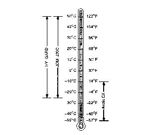
Use oil viscosity based on the expected air temperature range during the period between oil changes.
John Deere HY-GARD® is recommended.
Other oils may be used if they meet the following:
John Deere All-Weather Hydrostatic Fluid also may be used.
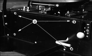
Removing Service Doors
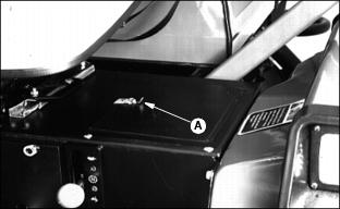
Raise latch (A) or turn tabs (B) and remove doors.
Cleaning Hydraulic System Breather
Checking Traction Unit Hydrostatic Transaxle/Hydraulic System Level
2. Lower cutting units to ground.
4. Check oil level when oil is cold.
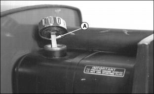
5. Remove dipstick (A). Wipe with a clean rag. Install dipstick.
6. If oil level is low, remove cap (B) and add John Deere HY-GARD® Transmission/Hydraulic Oil or an equivalent oil meeting John Deere J20C specifications.
7. Do not add oil above FULL mark.
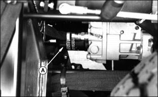
Changing Traction Unit Hydrostatic
Transaxle/Hydraulic System Oil
2. Run engine a few minutes to warm oil.
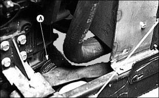
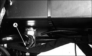
4. Remove drain plug (A) and drain oil in pan. Clean strainer (B)

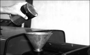
5. Fill with John Deere HY-GARD® Transmission/Hydraulic Oil or an equivalent oil meeting John Deere J20C specifications.
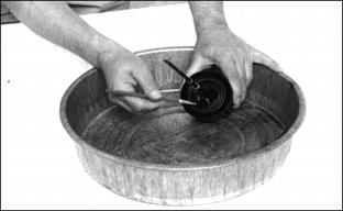
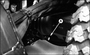
Replacing Hydrostatic Filter
2. Lower cutting units. Stop engine. Lock parking brake.
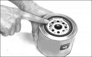
4. Using a filter wrench, remove filter (A).
5. Apply a film of oil to gasket of new filter.
6. Install filter. Turn filter until gasket meets base firmly.
7. Turn filter by hand one-half turn more.
8. Start engine and check filter for leaks.
9. Stop engine and check hydraulic oil level.
Replacing Hydraulic Oil
Filter
Replace filter after first 50 hours of operation and every 500 hours thereafter.
2. Apply a film of clean oil to new filter gasket.
3. Install filter. Turn filter until gasket contacts mounting surface. Turn filter by hand 1/2 turn more.
Checking Hydraulic Oil Level
2. Lower cutting units to ground.
4. Check oil level when oil is cold.
5. Remove dipstick (A). Wipe with a clean rag. Install dipstick.
7. If oil level is low, add John Deere HY-GARD® oil or an equivalent oil meeting John Deere J20C specifications. See Hydrostatic Drive Oil in this section.
8. Do not add oil above FULL mark.
Changing Hydraulic Oil
NOTE: Change oil at 500 hours or yearly, whichever comes first.
2. Remove plug (A) and drain oil.
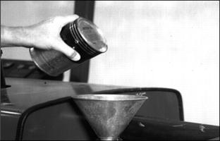
4. Fill reservoir with approximately 26.5 L (7 gal) (total in system) of oil. Use John Deere HY-GARD oil or an oil meeting John Deere J20C specifications. See Hydrostatic Drive Oil in this section.
6. Start engine. Cycle hydraulic control for 1 or 2 minutes.
7. Stop engine and check oil level.
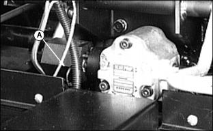
Transmission Neutral Adjustment
Do the following steps to eliminate any forward or reverse creep when in neutral position.
1. Lift machine until drive wheels are off the ground. Install jack stands under axle housings.
2. Disengage park brake and put seat switch in OVERRIDE position.
3. Move two-speed axle control lever to fast speed position
4. Start engine and operate at half throttle.
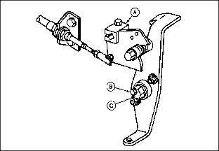
5. Loosen locking cap screw (B).
6. Turn eccentric nut (C) forward and backward until drive wheels stop turning. Turning eccentric nut will move transmission cam (A).
NOTE: Eccentric nut must be positioned rearward with respect to locking cap screw for correct adjustment.
7. Hold adjustment and tighten locking cap screw (B). Make sure adjustment did not change.
8. Put two-speed lever in neutral. Depress both forward and reverse speed pedals, then release.
9. Again put transaxle in fast speed. Check drive wheels for movement. Repeat steps 5 - 9 as necessary.
10. Stop engine and lower machine to the ground.
11. Check forward and reverse pedals for adjustment.
NOTE: If drive wheels continue to turn, check for worn or binding return-to-neutral linkage or too light of tension on neutral return spring. Check neutral return adjustment, below.
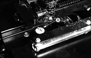
Transmission Neutral Return Adjustment
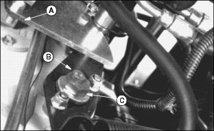
NOTE: The return spring length is only an initial setting. The length may vary according to operator's preference. Neutral return linkage shown removed for clarity.
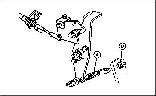
1. With travel pedals in neutral position, check length of return spring (A).
2. Loosen or tighten nuts (B) to adjust spring length.
3. Put two-speed axle lever in fast speed position.
4. Start engine and operate at fast idle. Check stopping distance of mower:
· Depress forward travel pedal fully.
· Note distance traveled after releasing travel pedal.
SPECIFICATIONS
Return Spring initial length 203 mm (8 inches).
Stopping distance at fast idle and fast speed 10.7 m (35 ft)
Results
Transmission must return to neutral when travel pedals are released. Time required to return to neutral is adjusted to operator's preference.