![]()
Introduction
Safety Signs
Controls
Operating
Replacement Parts
Service Machine Safely
Service Intervals
Service Lubrication
Service Engine
Service Transmission
Service Cutting Units
Avoid Injury From Contacting Blades
Stay Clear Of Rotating Drivelines
Adjusting Reel-To-Bed Knife Clearance
Readjust Reel-To-Bed Knife Clearance
Service Electrical
Service Miscellaneous
Troubleshooting
Storage
Assembly
Specifications
Warranty
John Deere Quality Statement
Copyright© Deere & Company

Service Cutting Units
Check Ground Conditions
· Clear mowing area of objects that might be thrown. Keep people and pets out of mowing area.
· Study mowing area. Set up safe mowing pattern. Do not mow under conditions where traction or stability is doubtful.
· First, test drive area with PTO OFF and mower lowered. Slow down when you travel over rough ground.
Avoid Injury From Contacting Blades
· Before you dismount to unplug or adjust cutting units:
- DISENGAGE reel drive by moving PTO switch to OFF position.
· Keep hands, feet and clothing away from cutting units when engine is running.
· DISENGAGE reel drive by turning PTO switch to OFF position when you are not mowing.
Stay Clear Of Rotating Drivelines
Entanglement in rotating driveline can cause serious injury or death:
· Wear close fitting clothing.
· STOP the engine and be sure PTO driveline is stopped before getting near it.
Cutting Units
NOTE: Refer to Safety section of this manual. Follow recommended precautions and safety practices shown.
Adjustments may affect each other. It is important that adjustments be made in the following sequence.
1. Adjust two-bolt gauge bar for desired height-of-cut.
2. Set units for the height-of-cut desired.
3. Adjust the reel-to-bed knife clearance.
4. Perform the backlapping operation.
5. Readjust reel-to-bed knife clearance.
Adjusting Height-Of-Cut
NOTE: All cutting units must be set at the same height to obtain an even cut. Floating units will not provide a quality cut in grass over approximately 38 mm (1-1/2 in.) tall.
1. Adjust reel-to-knife (see Adjusting Reel-To-Bed Knife in this section).
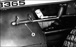
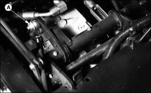
2. Raise cutting unit and engage transport locks (A) or remove from machine as desired.
NOTE: If rollers are adjusted to a position so gauge bar cannot be installed, raise either the front or rear roller or both to allow installation of the gauge bar.
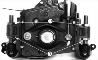
4. To raise rollers, loosen bottom adjusting nuts (B) and turn top adjusting nuts (C) clockwise on each end of cutting unit, alternating back and forth.
NOTE: Using a single-bolt adjusting gauge bar will not insure parallelism between rollers and may result in uneven height-of-cut.
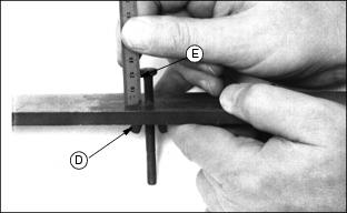
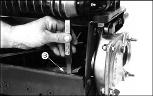
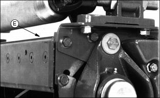
5. Loosen wing nut (D). Set height-of-cut by measuring from the top of the gauge to the bottom of the head of the bolt (E). Lock wing nut (D).
6. Hook head of bolt (E) over edge of bed knife.
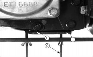
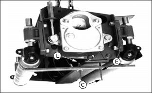
7. Loosen wing nut (F). Turn bolt (G) until gauge is parallel with bed knife. Measure distance between front (H) and rear (I) of the bottom of the bed knife to top of gauge. Distance should be the same.
NOTE: Be sure bolt (G) is not on mounting screw for bed knife.
When adjusting rollers, move both ends of roller equally, alternating from end to end. This will keep the adjusters from binding.
IMPORTANT: Avoid damage! Do not turn nuts beyond where the roller just touches the gauge bar or the gauge bar will bend. |
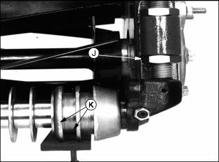
9. On grooved rollers, carefully turn bottom adjusting nut (J) until the first 2 ribs (K) of the machined portion of the roller just touches the gauge.
· This is determined by turning the roller and listening for the scratching sound from roller on gauge bar.
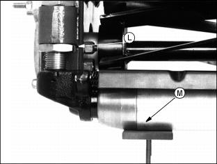
10. On solid rollers, carefully turn bottom adjusting nut (L) until the solid center piece of the roller (M) (not the end caps) just touches the gauge.
· This is determined by turning the roller and listening for the scratching sound. On rollers with scrapers, a screwdriver can be inserted in slot in scraper, lifted up, and screwdriver handle hooked under reel housing.
NOTE: Cutting units with no front roller (fixed position), set rear roller only.
11. After setting front and rear rollers on one end, lock jam nuts and recheck all gauge settings. Readjust if necessary.
12. Follow same procedure for other end of bed knife and rollers.
13. After setting second end, go back and check first settings to be sure they haven't moved. Readjust if necessary. Gauge can snugly be placed into position on either end when properly adjusted.
Adjusting Reel-To-Bed Knife Clearance
This adjustment, combined with the backlapping operation, will ensure a clean cut, as well as reduce wear, take less power, and reduce down time.
Reel-to-bed knife clearance should be checked BEFORE and AFTER backlapping.
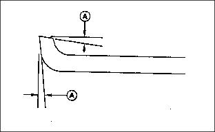
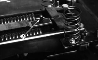
1. The cutting edge of the bed knife must be sharp and straight, and the relief angle should be 5 degrees (A) as shown.
· Otherwise, remove bed knife and bed knife support and have them ground as a complete unit.
IMPORTANT: Avoid damage! Do not allow the reel to interfere with the bed knife. Interference will cause heating and can damage reel and bed knife. |
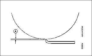
2. Use feeler gauges to set recommended reel-to-bed knife clearance (A) in the range for the grass to be cut.
· Finer textured grasses, such as rye grass or bent grass requires a close setting, but the setting should not be less than 0.05 mm (0.002 in.).
· They also require a sharp reel and bed knife to cut properly.
· Place a 0.05 mm (0.002 in.) feeler gauge (B) between bed knife and reel. Check at both ends of reel and 2 areas near the center.
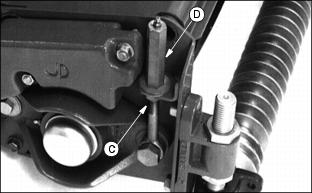
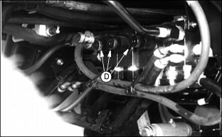
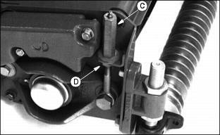
3. If adjustment is necessary, loosen jam nuts (C) and adjusting nuts (D) at both ends of the reel.
· Turn adjusting nuts (D) clockwise to raise reel.
· Turn jam nut (C) clockwise to lower reel.
· Adjust reel until 0.05 mm (0.002 in.) is reached across the entire reel and bed knife.
4. If adjustment is necessary, loosen jam nuts (C) and adjusting nuts (D) at both ends of the reel.
5. Tighten adjusting nuts (D) and jam nuts (C).
6. Recheck to insure reel has not moved. Readjust if necessary.
Backlapping Cutting Units
IMPORTANT: Avoid damage! The reel-to-bed knife clearance should be adjusted to approximately 0.076 mm (0.003 in.) at the ends. |
Backlapping cutting units must be done on a routine basis to prolong reel life, prevent downtime, and provide sharp cutting action.
1. Set parking brake and start engine.
2. Lower all cutting units to the ground.
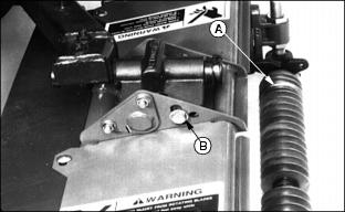
4. Pull up interlock switch (A), located under seat.
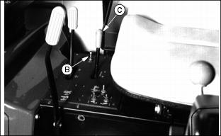
5. Move backlapping switch (B) to "N" (neutral position) for backlapping. Set throttle (C) on low idle.
NOTE: Cutting units may be backlapped separately. Left thumbscrew controls the left cutting unit. The center thumbscrew controls the right cutting unit. The right thumbscrew controls the three remaining units.
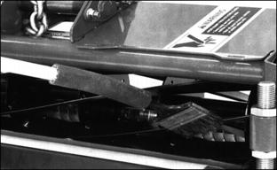
7. Turn thumbscrews (D) inward (clockwise) to turn reels in reverse and adjust speed. Thumbscrews are located on right side, behind fuel tank, and below battery.
· Reels must be turning backwards slowly enough so grinding compound will not be thrown off during backlapping.
8. Using a long-handled brush, carefully apply reel sharpening compound, uniformly, from one end of REEL to other. Repeat application in opposite direction. Allow unit to continue running backwards until reel is quiet.
IMPORTANT: Avoid damage! Do not operate units in the forward direction until reel sharpening compound is washed from the unit. Unless properly washed, the reels can be dulled by the compound. |
9. Periodically disengage PTO lever and shut engine off to visually check blade appearance.
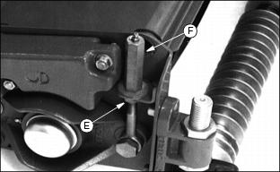
10. Inspect reel-to-bed knife clearance by loosening jam nuts (E) and turning adjusting nuts (F) and jam nuts (E) to proper clearance on both ends.
· Check for uniform clearance across entire bed knife. If clearance is not uniform, repeat Steps 7, 8, and 9 until clearance is uniform across entire bed knife.

11. Disengage PTO lever and shut off engine. Turn thumbscrews (D) fully counterclockwise. L
12. With reel stopped, use water to thoroughly wash off all reel sharpening compound.
Readjust Reel-To-Bed Knife Clearance
See Adjusting Reel-to-Bed Knife Clearance in this section.
Cutting Taller Grass
IMPORTANT: Avoid damage! When mowing tall grass in rough terrain, it is recommended to leave the front rollers on to protect the reels from striking any unseen objects. |
When cutting grass taller than approximately 38 mm (1-1/2 in.), the front roller tends to knock down grass affecting the quality of cut. In these conditions, it may be necessary to operate with cutting units in fixed position.
NOTE: This is recommended for smooth areas only, such as athletic fields, level parks, etc.
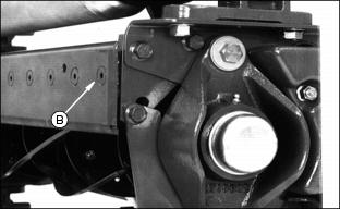
2. Remove scraper, if equipped.
3. Move cap screw, washer, and nut to fixed position (B).
Grinding The Bed Knife
NOTE: Bed knife removed for illustration purposes only.
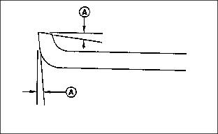
When grinding the bed knife, it is important to have a 5 degree relief angle on the top surface (A) and
front surface (A).
Replacing Bed Knife
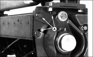
1. Remove 6 cap screws (A) attaching bed knife support to
cutting unit housing, 3 on each end.
2. Remove bed knife support, with bed knife attached, from cutting unit housing.
3. Remove and discard screws and nuts attaching bed knife to support. Discard bed knife.
4. Remove debris, corrosion, and rust from bottom surface of bed knife support.
5. Install both end screws (B) first, snug only. This will locate the bed knife.
6. Install rest of screws and nuts.
7. Torque nuts to 1/2 torque, approximately 26 N m (19 lb-ft), starting from the center out in both directions.
8. Finish torquing to full torque, 51 N·m (38 lb-ft), starting from the center out. Minimum torque is 45 Nm ( 33 lb-ft).
9. Put bed knife support and bed knife in a suitable grinder and grind until material is removed from the entire top surface of the bed knife lip.
10. Raise the reel at least 13 mm (1/2 in.) by turning the reel adjusting nut (C) clockwise and nut (D) counterclockwise.
11. Reinstall the bed knife support assembly, just snug cap screws (A).
12. Tap both ends of bed knife (E) towards reel with a brass hammer
to remove any play in bed knife support. Tighten cap screws to
43 Nm (32 lb-ft).
13. Set the height-of-cut. See Adjusting Height-of-Cut in this section.
14. Adjust the reel-to-bed knife. See Adjusting Reel-to-Bed Knife in this section.
15. Backlap reel. See Backlapping Cutting Units in this section.
16. Check the height-of-cut and adjust as necessary. See Adjusting Height-of-Cut in this section.
Adjusting Vertical Linkage
IMPORTANT: Avoid damage! Adjusting cutting units to raise higher than recommended can result in machine damage. |
Check cutting unit ground clearance with units lifted.
Adjust vertical link (A) to achieve 178 mm (7 in.) ground clearance when lift lever is in the raised position and engine is running.