![]()
Introduction
Safety Signs
Controls
Power Assist Rear Drive Switch
Engine Coolant Temperature Indicator
Hydraulic Oil Temperature Indicator
Hydrostatic Oil Temperature Indicator
Engine Alternator Volts Indicator
Cutting Unit(s) Toggle Switch(es)
Operating
Replacement Parts
Service Machine Safely
Service Intervals
Service Lubrication
Service Engine
Service Transmission
Service Cutting Units
Service Electrical
Service Miscellaneous
Troubleshooting
Storage
Assembly
Specifications
Warranty
John Deere Quality Statement
Copyright© Deere & Company

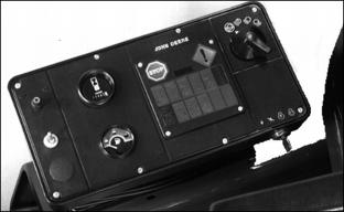
Controls
Control Console
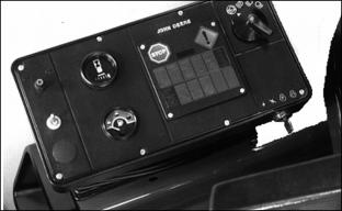
Console contains hour meter, fuel gauge, key switch, light switch, and warning light panel.
Hour Meter
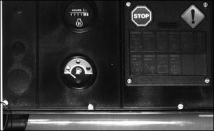
Registers hours of engine operation.
Hour meter will run when key is in "ON" position.
Fuel Gauge
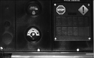
Indicates quantity of fuel in tank.
Stop to refuel before gauge reaches empty mark. Never allow a diesel engine to run out of fuel.
Key Switch
Turn key clockwise from OFF position (B) to ON position (C).
Turn key further clockwise to start position (E).
When key is released, it will return to ON position (C).
Turn key counterclockwise from (B) to (A) to operate accessories.
Light Switch
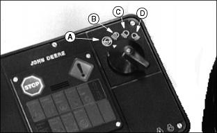
1. First one from left (A) is off.
2. Second one from left (B) is brights.
3. Third one from left (C) is running.
4. Forth one from left (D) is work lights.
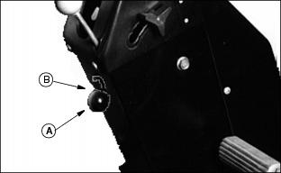
Power Assist Rear Drive Switch
Engage Power Assist by pushing the toggle switch up and disengage by pulling the switch down.
Warning Light Module
These lights indicate problems.
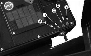
Stop Engine Indicator
IMPORTANT: Avoid damage! If Stop Engine indicator comes on, shut engine off immediately. Do not wait for cool down. Determine and correct the cause. |
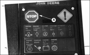
A red Stop Engine indicator (A) glows when a vital system malfunctions (such as cooling or lubrication).
A steady, audible tone also accompanies the glowing indicator.
Service Alert Indicator
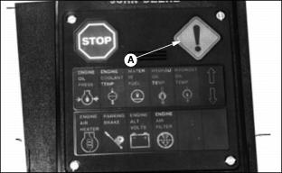
An amber Service Alert indicator (A) glows when a problem develops which does not require immediate engine shut down.
Observe gauges and indicators for possible cause. A maintenance check or a change in operation should be initiated as soon as possible.
Engine Oil Pressure Indicator
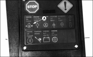
Indicator (A) and Stop Engine indicator will glow, and alarm will sound when engine oil pressure is low.
If lamp glows when engine is running, stop engine immediately. See your John Deere distributor.
Lamp will glow when engine is not running if switch is turned to ON.
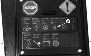
Engine Coolant Temperature Indicator
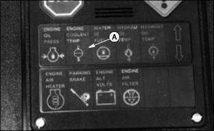
If temperature becomes excessive, indicator (A) will glow, the Stop Engine indicator will glow, and alarm will sound.
Stop engine and determine cause.
Water-In-Fuel Indicator
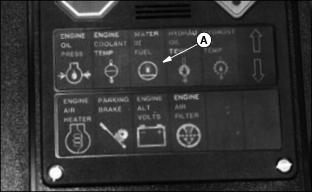
Indicator (A) and Stop Engine indicator will glow and alarm will sound when water gets in fuel.
Stop engine immediately and check fuel filter/water separator.
Hydraulic Oil Temperature Indicator
Indicator (A) and Stop Engine indicator will glow and alarm will sound when hydraulic oil temperature reaches 225°F (107°C).
Stop engine immediately and let hydraulic oil temperature cool. Check oil level. Check air screen and cooler for plugging.
Continued operation may cause higher temperatures resulting in damage.
Hydrostatic Oil Temperature Indicator
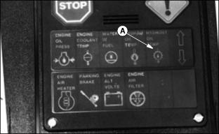
Indicator (A) and Stop Engine indicator will glow and alarm will sound when oil temperature in hydrostatic transmission reaches 225 °F (107°C).
Continued operation will cause higher temperatures resulting in damage.
Stop engine immediately and determine cause. Check air screen and cooler for plugging.
Engine Air Heater Indicator
During cool weather operation, indicator (A) comes on when key is turned to ON.
Start engine only after light goes out.
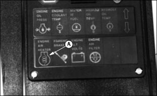
Parking Brake Indicator
Indicator (A) and Service Alert indicator will glow when parking brake is engaged, ignition switch is on, and forward or reverse pedal is depressed.
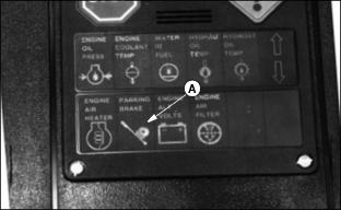
Engine Alternator Volts Indicator
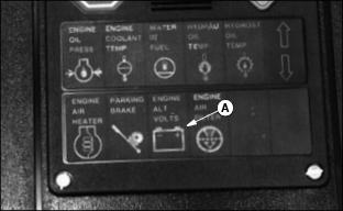
Indicator (A) and Service Alert indicator will glow when alternator is not charging the battery.
Engine Air Filter Indicator
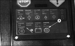
Indicator (A) and Service Alert indicator will glow when air cleaner element is dirty and needs servicing. Check and clean air filters only when this indicator light glows.
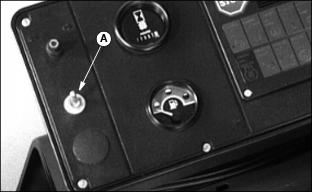
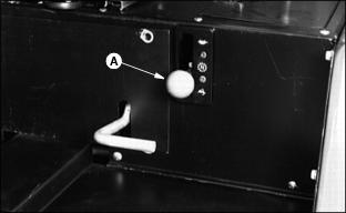
Adjustable Steering Wheel
Wheel position can be changed for operator's convenience.
Loosen knobs (A) on each side of steering column. Position wheel and tighten knobs.
Cruise Control
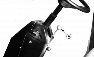
Use cruise control (A) to set and maintain position of forward speed control pedal.
See Using Cruise Control in Operating the Mower section.
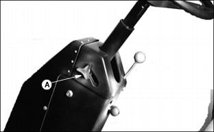
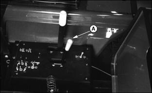
Parking Brake Lock
Depress parking brake pedal and lower knob (A) to engage lock until knob latches to bottom of slot.
IMPORTANT: Avoid damage! Be sure pedal and knob click down. Pedal must remain down when park brake is engaged. |
Release lock by depressing brake pedal and moving knob to position (B).
Foot Pedals
A - Service-Parking Brake Pedal
B - Forward Speed Control Pedal
C - Backward Speed Control Pedal
Use foot pedals to move machine forward or backward, and service-parking brake pedal to help stop machine.
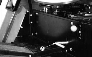
Two-Speed Axle Control Lever
Lever (A) must be in fast or slow range before mower will move.
Move lever to slow range 0 to 11.6 km/h (0 to 7.2 mph) for mowing, and fast range 0 to 18.8 km/h (0 to 11.7 mph) for transporting and mowing.
Throttle
Push throttle (A) forward to increase engine speed and pull rearward to decrease speed.
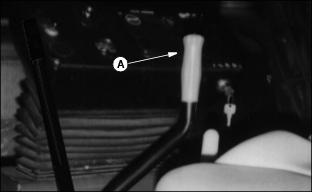
PTO Lever
Use lever (A) to engage or disengage PTO.
Push lever forward to engage PTO.
Pull lever rearward to disengage PTO.
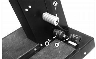
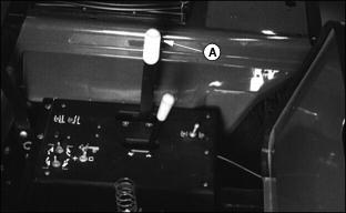
Cutting Unit(s) Toggle Switch(es)
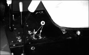
Use switches (A) to raise and lower wing cutting units individually.
These switches must be used to lower wing units if they are raised approximately 45 degrees above ground level.
Wing units will not lower on command from the cutting units lever if raised approximately 45 degrees above ground level.
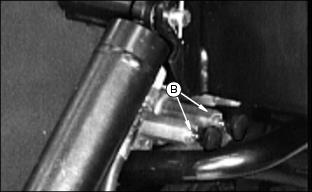
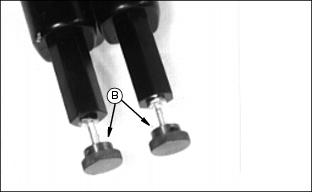
NOTE: In case of electrical failure of solenoid and/or switches, wing units can be raised by turning thumbscrews (B) all the way clockwise until both units are in fully raised position and ready for transporting.
Engage transport latches. Turn thumbscrews all the way counterclockwise.
Cutting Units Lever
Lever (A) raises/stops and lowers/starts all five cutting units.
Rapidly move lever to the extreme rearward limit of its travel and hold there until wing units raise sufficiently to maneuver mower, then release.
When released the lever will move to its neutral raised position.
Move the lever to the extreme forward limit of its travel to lower units.
Cutting units will operate when units are lowered if PTO is engaged. |
Holding the lever at its rear most limit for a longer time will cause wing units to continue to raise to their transport position.
Differential Lock
Use differential lock (A) for better traction on slopes and in slippery areas.
See Operating Differential Lock in Operating the Mower section.