![]()
Introduction
Safety Signs
Controls
Operating
Replacement Parts
Service Machine Safely
Service Intervals
Service Lubrication
Service Engine
Service Transmission
Service Cutting Units
Service Electrical
Checking Battery Electrolyte Level.
Charging The Battery (Continued)
Service Miscellaneous
Troubleshooting
Storage
Assembly
Specifications
Warranty
John Deere Quality Statement
Copyright© Deere & Company

Service Electrical
Service Battery Safely
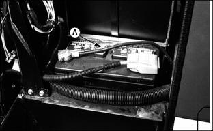
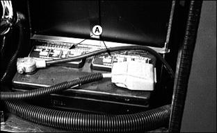
Disconnect battery negative (-) ground cable (A) before servicing if starting engine could possibly injure operator.
Use support stands when working under machine.
Fix damage immediately. Replace worn or broken parts.
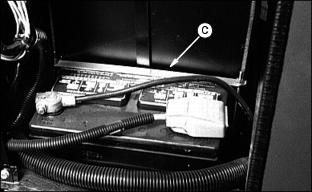
Checking Battery Electrolyte Level.
2. Remove battery manifold caps (A)
IMPORTANT: Avoid damage! DO NOT fill cells to the bottom of the filler neck (B). Electrolyte can overflow when battery is charged and cause damage. |
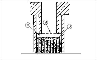
3. .Electrolyte (C) should be 1/4 in (6 mm) above plates (D).
4. Add distilled water if necessary.
5. Install manifold caps. Be sure manifold cap hose is behind positive cable.
Charging The Battery
Follow instructions on the battery charger or in the charger operator's manual, or use the instructions below as a guide.
· Wait until the battery has warmed to room temperature. Do not charge a frozen battery.
· Check the electrolyte level of each cell. (See Checking Battery Electrolyte Level in this section.)
· Install the battery cap(s) on the battery.
Turn OFF and unplug the charger before you connect cables to the battery or disconnect cables from the battery.
If the battery becomes warm to touch during charging:
· Stop charging the battery until it cools.
Charging The Battery (Continued)
1. Remove and clean battery. (See Cleaning Or Replacing Battery in this section.)
2. Check electrolyte level. (See Checking Battery Electrolyte Level in this section.)
3. Leave cell caps on battery while you charge it.
4. Connect positive (+) charger cable to positive (+) battery terminal.
5. Connect negative (-) charger cable to negative (-) battery terminal.
7. Charge battery. See CHARGING RATES on the next page.
8. Unplug charger cord. Remove charger cables.
Charging Rates
See your battery charger or charger operator's manual for information on charging. Or read the information below to FULLY CHARGE your battery.
For a charger with a CURRENT ADJUSTMENT CONTROL:
· Adjust the control to 10 amps.
· Charge the battery for 6-8 hours.
For a charger with a switch for MAINTENANCE FREE, DEEP CYCLE, or NORMAL (CONVENTIONAL) setting:
· Use the MAINTENANCE FREE or DEEP CYCLE setting.
For a charger with SLOW CHARGE, FAST CHARGE, or BOOST CHARGE setting:
· DO NOT use the BOOST CHARGE setting.
· Use the SLOW CHARGE setting:
· - For a charger rated at less than 10 amps.
· Use the FAST CHARGE setting:
· - For a charger rated at 10 amps.
NOTE: NOTE: Your charger may have an AUTOMATIC STOP to prevent charging the battery:
· When the battery is fully charged OR
· When the battery is not in condition to take a charge.
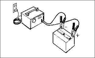
Using Booster Battery
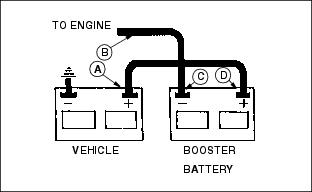
Connect positive (+) booster cable to booster battery positive (+) post (D).
Connect the other end of positive (+) booster cable to vehicle battery positive (+) post (A).
Connect negative (-) booster cable to booster battery negative (-) post (C).
Connect the other end of negative (-) booster cable to engine ground (B) away from battery.
Cleaning Or Replacing Battery
1. Stop engine. Lock parking brake. Remove key. Raise hood.
2. Disconnect negative (-) ground cable (A) first.
3. Disconnect positive (+) cable (B).
4. Clean battery using a damp cloth or rag. Keep dirt out of
battery cells.
5. Remove corrosion from terminals and cable clamps using a wire brush.
6. If battery is extremely dirty or needs replacing, remove battery hold-down (C) and remove battery.
7. Clean battery, battery terminals, cable ends, hold-down parts, and battery box with 1 part baking soda to 4 parts water. Keep solution out of battery cells.
8. Rinse all parts with clean water and let dry.
NOTE: If a new battery is needed, install a John Deere battery or an equivalent. See your John Deere distributor.
9. Install battery and secure using hold-down.
10. Connect positive (+) cable (D) to battery (shown).
11. Connect negative (-) ground cable (E) to battery. Connections must be tight.
12. Apply petroleum jelly on battery terminals to prevent corrosion.
13. Check cell caps. Vent holes must be open.
Replacing Fender HeadlIght
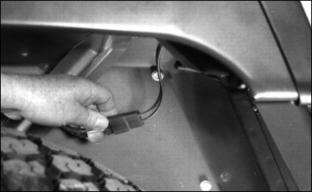
1. Disconnect wiring couplers.
2. Remove three screws and headlight.
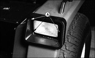
3. Install new headlight with screws (A).
Replace Fuses
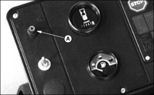
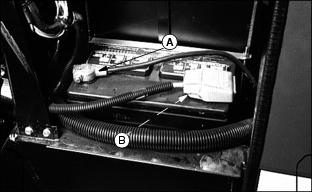
A 10 amp fuse (A) is located on the instrument panel and is in the circuit with the power assist rear wheel drive.
Four blade-type fuses are part of the electrical system. The fuses are located on the engine fire wall.
Replacing Fuses (Continued)
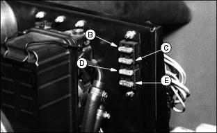
B - 25 Amp Fuse: Control Module