![]()
Introduction
Safety Signs
Controls
Operating
Replacement Parts
Service Machine Safely
Service Intervals
Service Lubrication
Service Engine
Service Transmission
Service Cutting Units
Service Electrical
Service Miscellaneous
Troubleshooting
Storage
Assembly
Hose Routing (Control Valve Area)
Hose Routing (Left And Right Wing Motors)
Specifications
Warranty
John Deere Quality Statement
Copyright© Deere & Company

Assembly
Activate Battery

IMPORTANT: Avoid damage! To prevent damage to tractor from spilled electrolyte, remove the battery from the tractor. |
1. Remove the battery from the vehicle.
2. Remove and discard tape from across battery cells.
3. Remove and discard blue cell caps.
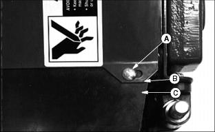
· Only use battery acid with a 1.265 specific gravity. Slowly add acid (B) to each cell. The solution should be 1/4 in. (6 mm) above plates (C), but NO HIGHER THAN 1/4 in. (6 mm) from the bottom of the filler neck (A).
5. Install the battery manifold cap from the bag of parts. Be sure manifold cap hose is behind positive cable.
6. Charge the battery for a MINIMUM of 30 minutes at 5-10 amps. If your battery charger has a Deep Cycle or Maintenance Free setting, use this setting to charge the battery. Failure to charge the battery before use will reduce battery performance and life.
8. Connect red positive (+) cable (A) to battery. Apply petroleum jelly or silicone spray to terminal to prevent corrosion. Make sure connection is tight.
9. Push red positive cover (B) over positive terminal.
10. Connect black negative (-) cable (C) to battery. Apply petroleum jelly or silicone spray to terminal to prevent corrosion. Make sure connection is tight.
Install Front Roller
1. Remove cap plugs from ends of roller shaft.
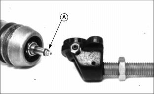
2. Insert grease zerks (A) in both ends.
3. Thread nut (B) approximately 1 in. from bottom of threaded adjuster shaft.
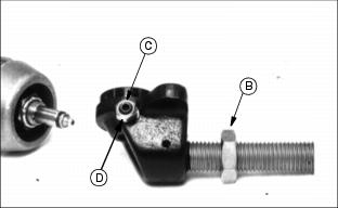
4. Thread set screw (C) half way into adjuster with hex hole for allen wrench facing out.
5. Thread jam nut (D) onto set screw.
6. On adjuster for other end, just thread nut onto adjuster shaft approximately 1 in. from bottom of adjuster. There is no hole for set screw in this adjuster.
Tip reel on its back roller side for easier front roller assembly. Adjuster mounting brackets are offset. If grass is to be cut 1-1/2 in. or less, "long" end (E) of bracket goes toward the bed knife. This is the way the rear rollers are installed from the factory. If grass is to be cut 1-1/2 in. or higher, "short" end (F) of bracket goes toward the bed knife.
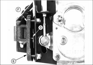
7. Align pin (G) in adjuster mounting bracket with hole in attaching bracket.
8. Attach adjuster mounting bracket with cap screws.
IMPORTANT: Avoid damage! One end of roller shaft has flats on it. The height adjuster with the set screw also has flats in the roller shaft mounting hole. The two must be on the gear box end of reel. |
NOTE: FINGER TIGHTEN cap screws. Bracket must be allowed to move until roller is assembled.
9. Attach height adjusters to roller shaft. Flats on roller shaft and adjuster MUST be on gear case end of reel.
10. Insert threaded shafts through adjuster mounting brackets.
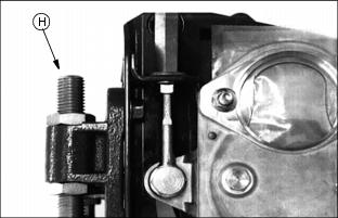
11. Thread nuts (H) onto shafts FINGER TIGHT only.
IMPORTANT: Avoid damage! Tightening sequence MUST be followed. This will self-align the rollers to the adjusters and brackets. |
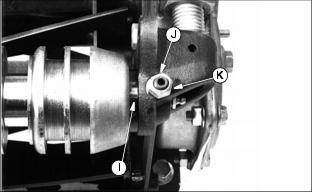
12. Center roller between right and left height adjusters. Gap (I) should be the same on both ends. Tighten set screw (J) and jam nut (K).
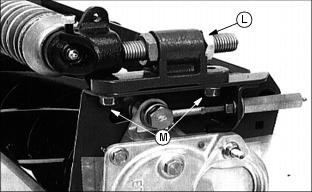
13. Tighten top nuts (L) on left and right-hand adjusters with 36 mm wrench provided with machine.
14. Tighten adjuster mounting bracket nuts (M) on left and right sides of reel.
Install Scraper Blade
There is a right and left hand spring. Each spring has a long and short leg.
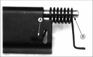
1. Insert short leg (A) of springs through slots in both ends of scraper.
2. Slide rod (B) through scraper and springs.
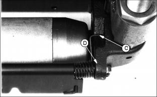
3. Place long leg of spring in groove (C) of height adjuster. Press down and push rod into hole (D) of height adjuster.
4. Follow same procedure for other end of scraper.
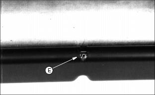
5. Align hole in rod with slot in center of scraper and drive roll pin (E) in flush with top of scraper.
NOTE: To clean scraper, place screw driver in either slot (F) in scraper and push towards reels. Scraper will lift for easier cleaning under it.
Install Grass Deflector
1. Install grass deflector UNDER slotted bracket.
2. Install carriage bolts (A) through slots, then deflector.
3. Assemble flat washer (B) and lock nut (C) under deflector.
4. Tighten nuts until washers are only up to deflector. Deflector MUST be able to move after tightening to allow for expansion and contraction due to temperature changes.
Install Reel Motor
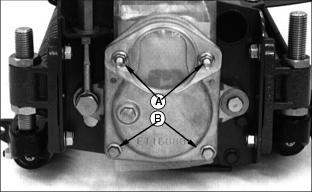
1. Remove 4 nuts (A), 2 bottom bolts (B), and gear cover.
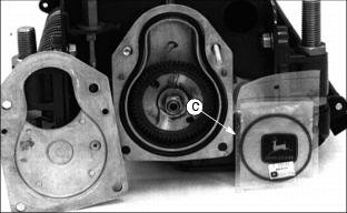
2. Remove motor O-ring (C) from inside gear case.
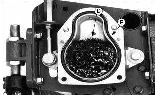
3. Fill gear case to top of reel drive gear (D) with John Deere Cotton Picker Spindle Grease or other SAE Multipurpose Grease meeting NLGI Consistency Number 00. See Cutting Unit Gear Case Grease in this section.
4. Be sure gear case O-ring (E) is in place.
5. Install gear case cover and fasten with 2 bottom bolts and nuts ONLY.
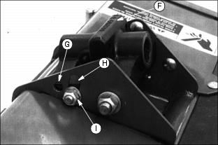
6. Remove reel pivot (F) from machine and install on reel cutting unit.
7. Pivot can be installed in fixed position (G) or float position (H).
NOTE: When installing in float position (H), slowly tighten lock nut (I) only to the point where there is still "full free float" in slot.
8. Free motor from lift arm on machine and remove protective cap from motor gear
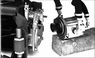
10. Install O-ring (J) (removed in step 2) to motor and assemble motor to gear box with top 2 gear box bolts (K) and nuts.
11. Grease zerks (L). See Extreme Pressure or Multipurpose Grease in Lubrication and Maintenance section.
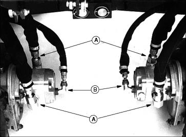
Hose Routing (Front Motors)
1. Locate four pressure hoses (A) (larger) for both front motors vertically.
2. Locate drain fittings (B) (smaller) for both front motors 60 degrees off vertical and toward the back.
Hose Routing (Center Motor)
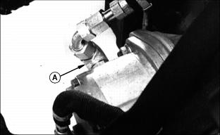
1. Locate front fitting (A) 30 degrees off vertical and away from center of cutting unit.
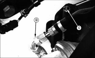
2. Locate fitting (B) toward center of cutting unit. Allow clearance for access to adjuster (C).
3. Locate rear fitting (D) 35 degrees from vertical and toward center of cutting unit.
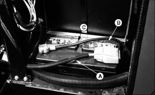
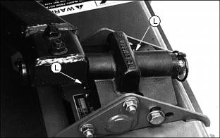
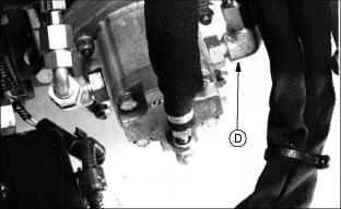
Hose Routing (Control Valve Area)
1. Remove any tie bands that tie hose (A) to hose (B) at location (C).
NOTE: DO NOT remove hose clamp from drain hose at location (D).
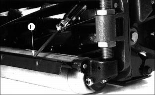
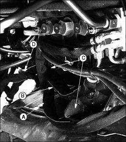
Hose Routing (Left And Right Wing Motors)
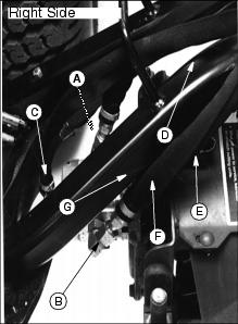
1. Locate front fitting (A) 15 degrees from vertical and toward center cutting unit.
2. Locate rear fitting (B) 35 degrees from vertical and toward center of cutting unit.
3. Locate drain fitting (C) vertical.
4. Route all three hoses over lift arm at location (D).
NOTE: This photo shows unit in the slightly raised position with it contacting stop (E). In this position, the rear hose (F) must clear lift arm at location (G).