![]()
Introduction
Safety Signs
Controls
Operating Machine
Operating Cutting Units
Replacement Parts
Service Machine Safely
Service Interval Chart
Service Lubrication
Service Engine Gas Units
Engine Warranty Maintenance Statement
Raising and Lowering Engine Cowling
Raising and Lowering Operator Seat
Changing Engine Oil and Filter
Cleaning Oil Cooler Coils and Radiator Cooling Fins
Check Radiator Hoses, Air Intake Hose and Clamps
Checking and Adjusting Fan Belt
Service Engine Diesel Units
Service Hydraulics & Transmission
Service Cutting Units
Service Electrical
Service Miscellaneous
Troubleshooting
Storing Machine
Assembly
Specifications
Warranty
John Deere Service Literature
John Deere Quality Statement
Copyright© Deere & Company

Service Engine - Gas Units
Engine Warranty Maintenance Statement
Maintenance, repair, or replacement of the emission control devices and systems on this engine, which are being done at the customers expense, may be performed by any nonroad engine repair establishment or individual. Warranty repairs must be performed by an authorized John Deere dealer.
Avoid Fumes

- If it is necessary to run an engine in an enclosed area, use an exhaust pipe extension to remove the fumes. |
Engine Oil
Use oil viscosity based on the expected air temperature range during the period between oil changes.
The following John Deere oils are preferred:

The following John Deere oils are also recommended if above preferred oil is not available:
· TORQ-GARD SUPREME® - SAE 5W-30
Other oils may be used if all the above John Deere oils are not available and they meet one of the following:
· API Service Classification SH and SG
· CCMC Specifications G5 and G4
· Military Specification MIL-L-2104F
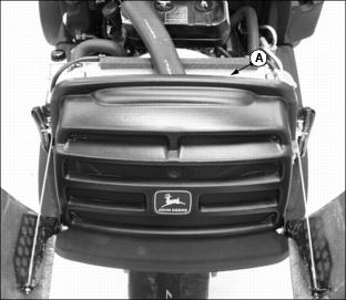
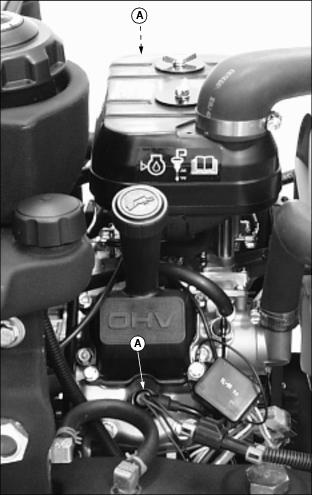
Raising and Lowering Engine Cowling
IMPORTANT: Avoid damage! To avoid damage to the greens mower, Do Not operate the machine with the cowling in the raised position. |
1. Park greensmower on a hard, level surface.
2. Stop the engine and engage park brake.
· Turn button (A) clockwise to unlock cowling.
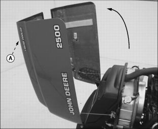

· Turn button (A) counterclockwise to lock cowling in the lowered position.
Raising and Lowering Operator Seat
Carefully raise and lower the seat to avoid pinching fingers. |
NOTE: Adjust operator seat rearward as far as possible. See Adjusting Seat in the Operating section.
Raising the Seat
· Raise and tilt operator seat forward.

· Remove prop rod (A) secured in stored position under operator seat platform.
· Install prop rod in channel slot (B).
Lowering the Seat
· Remove prop rod from channel notch.
· Secure prop rod in stored position under operator seat platform.
Checking Engine Oil
1. Park greensmower on a hard, level surface.
2. Stop engine and engage park brake.
IMPORTANT: Avoid damage! Help prevent dirt and other contaminants from entering the oil dipstick tube location. Clean area around dipstick before removing. |
4. Remove dipstick (A). Wipe with a clean cloth.
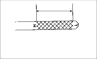
6. Remove dipstick. Check oil level on dipstick; oil level should be between the "H" (High) and "L" (Low) marks on the dipstick.
· If oil is low, add oil to bring oil level no higher than the "H" (High) mark on the dipstick. (See Engine Oil in this section for correct oil application.)
· If oil level is above the "H" (High) mark, drain to proper level.
Changing Engine Oil and Filter
NOTE: Change engine oil after the first 20 hours of break-in operation.
The recommended service interval for changing engine oil and filter under normal conditions is every 200 hours. Severe or unusual conditions may require a more frequent service interval. (See Service Interval Chart section for reference.)
1. Run engine to warm the oil.
2. Park greensmower on a hard, level surface.
3. Stop engine and engage park brake.
· Place container under oil drain location.
NOTE: Attaching a section of plastic or rubber hose to the end of drain valve will help prevent engine oil from draining onto the center lift arm.
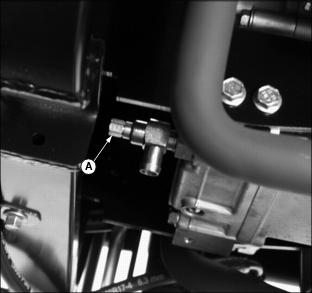
· Open drain valve (A) to drain oil.
· Locate filter under right side of engine.
· Turn filter counterclockwise to remove.
7. Apply a film of clean engine oil on gasket of new filter.
· Turn filter clockwise until gasket makes contact with mounting surface. Tighten 1/2-3/4 turn after gasket contact.
9. Close oil drain valve (A). DO NOT overtighten.
11. Add approximately 1.8 L (1.9 qt) of engine oil. (See Engine Oil in this section for the correct application.)
· Run engine at a slow "t" throttle speed for approximate two minutes.
· Check area under engine for oil leaks.
15. After approximately two minutes check engine oil level.
IMPORTANT: Avoid damage! Help prevent dirt and other contaminants from entering the oil dipstick tube location. Clean area around dipstick before removing. |
16. Remove dipstick (D). Wipe with a clean cloth.
18. Remove dipstick. Check oil level on dipstick; oil level should be between the "H" (High) and "L" (Low) marks on the dipstick.
· If oil is low, add oil to bring oil level no higher than the "H" (High) mark on the dipstick. (See Engine Oil in this section for correct oil application.)
· If oil level is above the "H" (High) mark, drain to proper level. DO NOT overfill.
20. Close rear engine cowling.
Cleaning Rear Grill Screen
IMPORTANT: Avoid damage! The rear grill screen must be clean to prevent engine from overheating and to allow adequate air intake. |
1. Park greensmower on a hard, level surface.
2. Stop engine and engage park brake.
4. Remove rear grill screen (A) from position behind engine radiator.
5. Clean screen with compressed air.
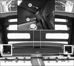
· Install grill screen notches (B) onto each bracket mounting pin (C).
Cleaning Oil Cooler Coils and Radiator Cooling Fins
IMPORTANT: Avoid damage! Oil cooler coils and radiator cooling fins must be clean to prevent overheating. |
1. Park greensmower on a hard, level surface.
2. Stop engine and engage park brake. Allow engine to cool.
4. Remove rear grill screen. (See Cleaning Rear Grill Screen in this section.)
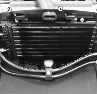
5. Release latches (A) securing oil cooler to the radiator mounting bracket.
· Carefully move oil cooler away from the radiator.
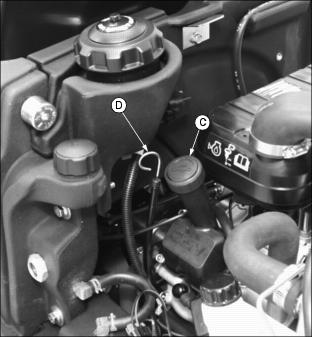
6. Remove dirt and debris from oil cooler coils (C) and radiator fins (D) using compressed air or water.
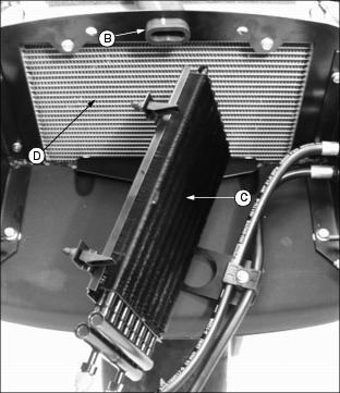
· Check oil cooler coils and radiator fins for damage.
Servicing Air Cleaner Element
IMPORTANT: Avoid damage! Help prevent premature engine damage. DO NOT run engine without both air cleaner elements installed. |
NOTE: It may be necessary to check the air cleaner element more frequently if operating greensmower in dusty conditions.
Check Air Cleaner Element
1. Park greensmower on a hard, level surface.
2. Stop engine and engage park brake. Allow engine to cool.
4. Clean any dirt or debris surrounding the air cleaner assembly before removing cover.
5. Remove air cleaner cover (A) by loosening both wing nut bolts (B).
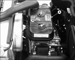
7. Inspect foam precleaner (C) and inside of paper element (D) for dirt and debris without removing.

Service Air Cleaner Element
IMPORTANT: Avoid damage! Engine damage or failure can occur from dirt or debris in the carburetor. · Take care when removing filter element to prevent dirt and debris from entering the carburetor. |
1. If foam precleaner is dirty, carefully remove paper filter and precleaner away from the air cleaner housing.
2. Carefully lower air cleaner cover over carburetor opening.
3. Remove foam precleaner (C) from paper element (D).
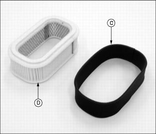
NOTE: DO NOT wash paper element.
4. Wash precleaner in a solution of warm water and liquid detergent.
5. Rinse precleaner thoroughly. Squeeze out excess water into a dry cloth until precleaner is completely dry.
6. Put approximately 30 ml. (1 oz.) of clean engine oil onto precleaner. Squeeze precleaner to distribute oil evenly. Squeeze out excess oil with a clean cloth.
8. Replace paper element with a new element only if damaged or very dirty.
9. Install foam precleaner (C) onto new paper element (D).
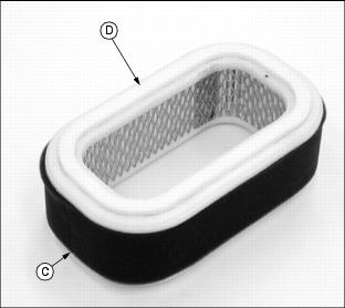
10. Carefully raise air cleaner cover. Install air cleaner element into air cleaner housing.
11. Install air cleaner cover.
· Tighten cover in position with wing nut bolts.
12. Close rear engine cowling.
Check Radiator Hoses, Air Intake Hose and Clamps
1. Park greensmower on a hard, level surface.
2. Stop engine and engage park brake. Allow engine to cool.

· Check hose for cracks or damage.
5. Check upper radiator hose (C).
· Check hose for cracks or damage.
6. Check lower radiator hose (D).

· Check hose for cracks or damage.
Service Cooling System Safely
Engine Coolant
The following John Deere coolant is preferred:
· PRE-DILUTED DIESEL ENGINE ANTI-FREEZE/SUMMER COOLANT (TY16036).
If preferred pre-diluted coolant is not available, the following John Deere concentrate is recommended:
· DIESEL ENGINE ANTI-FREEZE/SUMMER COOLANT CONCENTRATE (TY16034).
These coolants exceed industry specifications: ASTM D5345, D4656, D4985, D3306, and GM6038. They are designed with 5-year or 5000 hour long life formulation (subject to testing annually for conditioner level) for use in all heavy duty diesel engines. These coolants have a coolant conditioner added to help protect against liner pitting and cavitation.
If neither of the above coolants is available, use an ethylene glycol base coolant that meets the following specification:
Check container label before using to be sure it has the appropriate specifications for your machine. Use coolant with conditioner or add conditioner to coolant before using.
IMPORTANT: Avoid damage! To prevent engine damage, DO NOT use pure antifreeze or more than 50% antifreeze in the cooling system. DO NOT mix or add any other type additives to the cooling system. |
If using concentrate, mix approximately 50 percent antifreeze with 50 percent distilled or deionized water before adding to cooling system. This mixture will provide freeze protection to -37 degrees C
(-34 degrees F).
Certain geographical areas may require lower temperature protection. See the label on your antifreeze container or consult your John Deere dealer to obtain the latest information and recommendations.
The preferred antifreeze provides:
· Corrosion-resistant environment within the cooling system.
· Protection against liner pitting and cavitation.
· Compatibility with cooling system hose and seal material.
· Protection during cold and hot weather operations.
Engine Coolant Drain Interval
When using PRE-DILUTED DIESEL ENGINE ANTI-FREEZE/SUMMER COOLANT or DIESEL ENGINE ANTI-FREEZE/SUMMER COOLANT CONCENTRATE (TY16034) coolants, drain and flush the cooling system and refill with fresh coolant mixture every 60 months or 5,000 hours of operation, whichever comes first.
If above John Deere Service coolants are not being used: drain, flush, and refill the cooling system with fresh coolant mixture every 24 months or 600 hours of operation, whichever comes first.
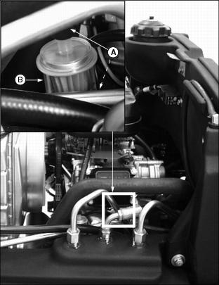
Checking Coolant Level
1. Park greensmower on a hard, level surface.
2. Stop engine and engage park brake. Allow engine to cool.
4. Check recovery tank (A) coolant level:
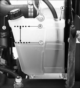
· If engine is warm, coolant level should be between the "H" (HIGH) line (B) and the "L" (LOW) line (C).
· If engine is cold, coolant level should be at the "L" (LOW) line (C) on the recovery tank.
5. Remove recovery tank cap (D) to add coolant.
6. If coolant is low, add pre-diluted coolant or specified ratio of antifreeze and water. (See Engine Coolant in this section for the correct application.)
7. Install and tighten recovery tank cap.
8. Clean debris from rear grill screen, oil cooler coils and radiator cooling fins. (See Cleaning Rear Grill Screen and Cleaning Oil Cooler Coils and Radiator Cooling Fins in this section.)
9. Check condition of hoses. Check for leaks or loose connections. (See Check Radiator Hoses, Air Intake Hose and Clamps in this section.)
Draining Cooling System
IMPORTANT: Avoid damage! Help prevent damage to the engine: · DO NOT operate engine without coolant. · DO NOT pour coolant into the radiator when the engine is hot. |
1. Park greensmower on a hard, level surface.
2. Stop engine and engage park brake. Allow engine to cool.
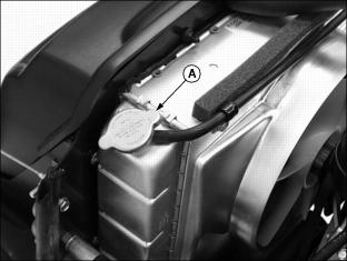
4. Slowly open radiator cap (A) to the first stop to release all pressure.

5. Close radiator cap tightly.
NOTE: A section of plastic or rubber hose can be used to divert fluid away from the greensmower.
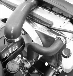
6. Open radiator petcock (B). Drain coolant into a pan.

7. When coolant drains from the recovery tank, remove radiator cap.
8. After all coolant has drained, close radiator petcock.
9. Flush cooling system. (See Flushing Cooling System in this section.)
Flushing Cooling System
Turn radiator cap using a thick rag or glove to protect your hand. |
IMPORTANT: Avoid damage! To prevent engine damage: |
1. Fill cooling system with clean water and John Deere Cooling System Cleaner, or John Deere Cooling System Quick Flush or an equivalent. Follow directions on the can.
2. Install and tighten radiator cap (A).
3. Start and run engine until it reaches operating temperature.
· Drain cooling system immediately before rust and dirt settle. (See Draining Cooling System in this section).
Filling Cooling System
1. Fill cooling system. (See Engine Coolant in this section for proper antifreeze application.)
· Certain geographical areas may require lower temperature protection. See the label on your antifreeze container or consult your John Deere distributor to obtain the latest information and recommendations.
· John Deere Cooling System Sealer or its equivalent may be added to the radiator to seal leaks. Do not use any other additives in the cooling system.
2. Install and tighten radiator cap.
3. Run engine until it reaches operating temperature.
5. Check recovery tank (A) coolant level:
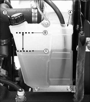
· If engine is warm, coolant level should be between the "H" (HIGH) line (B) and the "L" (LOW) line (C).
· If engine is cold, coolant level should be at the "L" (LOW) line (C) on the recovery tank.
6. Remove cap (D) from recovery tank to add coolant if necessary.
7. Check condition of coolant system hoses and clamps. (See Check Radiator Hoses, Air Intake Hose and Clamps in this section.)
Checking Spark Plugs
NOTE: Engine has two spark plugs, one on each side of engine.
In Canada, replace spark plugs with resistor plugs only.
1. Stop engine and engage park brake. Allow engine to cool.
3. Clean area around both spark plugs.
4. Disconnect spark plug wire (A) from each plug.
5. Remove and inspect spark plugs:
· Check plugs for cracked porcelain, pitted or damaged electrodes or other damage.
· Clean spark plugs carefully with a wire brush.
· Replace spark plugs as necessary.
6. Check and adjust spark plug gap (B).

· Gap must be 0.7 mm (0.028 in.).
7. Install and tighten spark plugs. Tighten plugs to
25 N·m (18 lb-ft.).
8. Install both spark plug wires.
Replacing Fuel Filter
1. Park greensmower on a hard, level surface.
2. Stop engine and engage park brake. Allow engine to cool.
4. Locate fuel filter on right side of engine.
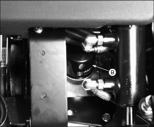
5. Slide hose clamps (A) away from fuel filter (B).
6. Disconnect hoses from filter.
· Place a drain pan under hoses to catch any fuel that may be left in the hoses.
NOTE: Make sure fuel filter is installed with arrow pointing in direction of fuel flow toward engine.
· Connect hoses to new filter.
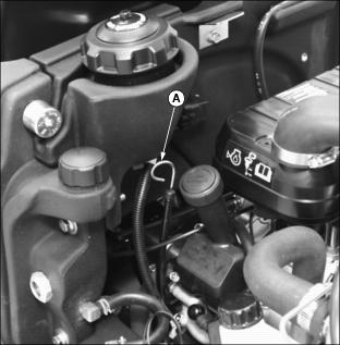
Checking and Adjusting Fan Belt
Check Belt Tension
1. Park greensmower on a hard, level surface.
2. Stop engine and engage park brake. Allow engine to cool.
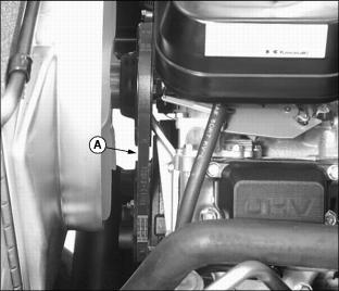
· Inspect belt for excessive wear, damage or stretching while in position on the fan and flywheel sheaves.
· Apply thumb pressure to the belt approximately halfway between the sheaves. Belt should deflect inward approximately 9.5 mm (3/8 in.).
Adjust Belt Tension
NOTE: Removal of engine spark plugs will allow for easier rotation of sheave assembly when performing this service procedure.
1. Remove both engine spark plugs.
2. Remove outer half of sheave (B).
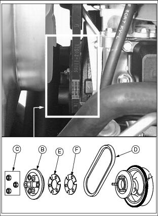
· Remove three hex nuts (C) attaching outer half of sheave to the engine flywheel.
3. Remove fan belt if replacement is necessary (D).
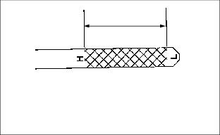
NOTE: To allow sheaves to fit closer together and increase belt tension, remove spacer shim(s). The minimum number installed at the factory is one 0.6 mm thick shim (E) and the maximum is two 0.6 mm thick shims and one 1.2 mm thick shim (F). Removed spacers can be installed between or outside of outer sheave half.
Spacer shim(s) must remain in position when a new belt is installed.
4. Remove spacer shim(s) to increase belt tension.
5. Loosely install belt between sheave halves while installing outer half of sheave onto three threaded flywheel studs.
6. Rotate sheave assembly as nuts are tightened to allow belt to center in sheave halves and not be pinched in an OFF-CENTER position.
· Tighten nuts to 20-30 N·m (15-21 lb-ft.).
· Apply thumb pressure to the belt approximately halfway between the sheaves. Belt should deflect inward approximately 9.5 mm (3/8 in.).
Adjusting Carburetor
NOTE: Carburetor is calibrated by the engine manufacturer and should not require any adjustments.
If engine is operated at altitudes above 1829 m (6,000 ft.), some carburetors may require a special high altitude main jet. See your John Deere dealer.
Possible engine surging will occur at high rpm with no load (with transmission in "N" neutral and the mow/transport switch in the OFF position.) This is a normal condition due to the emission control system.
If engine is hard to start or runs rough, check the troubleshooting section of this manual.
After performing the checks in the troubleshooting section and your engine is still not performing correctly, contact your John Deere dealer.