![]()
Introduction
Safety Signs
Controls
Operating Machine
Operating Cutting Units
Replacement Parts
Service Machine Safely
Service Interval Chart
Service Lubrication
Service Engine Gas Units
Service Engine Diesel Units
Service Hydraulics & Transmission
Service Cutting Units
Service Electrical
Service Miscellaneous
Troubleshooting
Storing Machine
Assembly
Install Rear Steering Wheel Assembly
Checking and Connecting the Battery
Check Machine Safety Interlock System
Check and Adjust Lift Arm Stops
Specifications
Warranty
John Deere Service Literature
John Deere Quality Statement
Copyright© Deere & Company

Assembly
Identify Parts

F - Drive Wheels (Smooth Tires Shown)
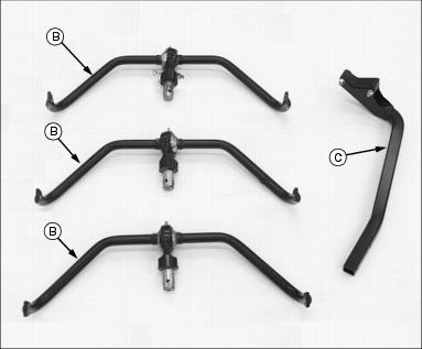
Bag of Parts List


NOTE: The Model 2500 Tri-Plex Greensmower is packaged and shipped from the factory without wheels. Customer will select wheel option preferences at time of purchase.
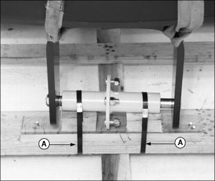
Prepare for Assembly
1. Remove greensmower from shipping crate.
2. While positioned on the shipping crate base, attach a safe lifting device to the rear of the greensmower.
3. Cut steel bands (A) securing rear of greens mower to shipping crate pedestal.
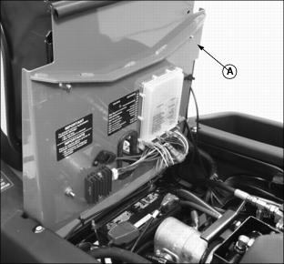
Install Rear Steering Wheel Assembly
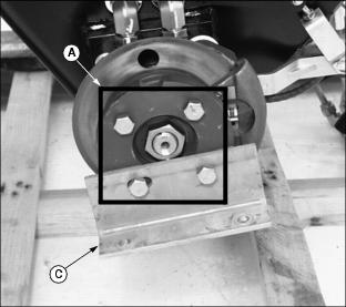
1. Remove hex nut (A) securing rear steering wheel hub assembly in position on rear yoke.

2. Lift rear of greens mower with a safe lifting device.
3. Remove axle (B), bushing (C), hub assembly (D) and bushing (E) from yoke.

4. Check rear steering wheel tire inflation pressure.
· Keep tire inflated to 69-83 kPa (10-12 psi).
5. Install rear steering wheel.
· Remove four wheel nuts from the hub assembly.
· Install hub (D) onto wheel with four wheel nuts (E). Tighten hardware alternately to 81-95 N·m
(60-70 lb-ft.).

· Install axle (B) through right side of yoke, bushing (C), hub assembly (D), bushing (E) and left side of yoke.

· Fasten wheel to yoke with hex nut (A). Tighten hex nut side-to-side to eliminate freeplay. DO NOT overtighten, wheel must have the ability to rotate freely.
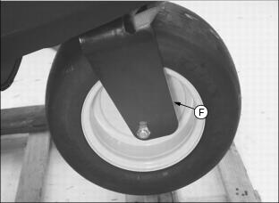
6. Lower rear of greens mower.
7. Lubricate steering wheel bearings (F) with John Deere Multi-Purpose HD Lithium Complex Grease or an equivalent.
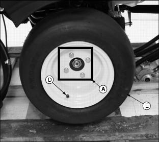
Install Front Drive Wheels
1. Loosen four wheel bolts (A) stored in each front drive wheel hub.

2. Remove cap screws (B) and locknuts securing shipping brackets to shipping crate base.
3. Raise front of greens mower with a safe lifting device.
4. Remove wheel bolts (A) and shipping brackets (C) from each front drive wheel hub.
· Discard both shipping brackets.
5. Check tire inflation pressure of each front drive wheel.
· Keep tire inflated to 69-83 kPa (10-12 psi).
NOTE: Make sure each drive wheel valve stem (D) faces to the outside.
6. Install front drive wheels (E).
· Install one drive wheel to each hub using four wheel bolts (A). Tighten until snug.
7. Lower front of greens mower.
8. Tighten wheel bolts alternately until recommended torque value is reached.
· Tighten wheel bolts to 81-95 N·m (60-70 lb-ft.).
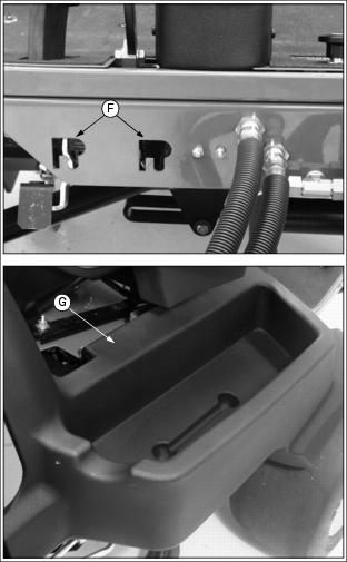
9. Install front cutting reel motors into "R" shaped holes (F) stamped in the front of the operator platform. Center cutting reel motor should be laid inside the fuel tank tray (G).
10. Carefully move greens mower off shipping crate base.
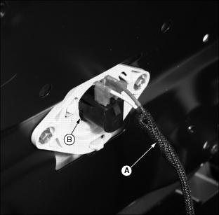
Install Operator Seat
NOTE: For maximum operator comfort, use forward seat pan mounting holes when installing the seat.
1. Connect wire harness (A) to safety switch (B) located under operator seat.
2. Install seat to platform slide rail assembly.
· Install rear of seat onto slide rail studs (C).

· Fasten rear of seat in position with two 5/16" flanged lock nuts (D). Do not tighten.
· Fasten front of seat to slide rail assembly with two 5/16" x 5/8" hex bolts (E).

Install Steering Wheel
1. Coat splined steering wheel shaft (A) with multi-purpose grease.
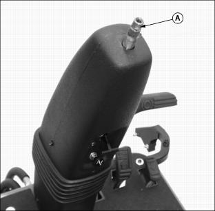
Picture Note: Pedestal on liquid cooled gas model shown.
2. With rear wheel straight and facing forward, install steering wheel (B) onto the shaft.

3. Install 5/8" hex nut (C) and tighten until snug.
Checking and Connecting the Battery
1. Adjust operator seat rearward as far as possible. (See Adjusting Seat in the Operating section.)
2. Raise and tilt operator seat (A) forward.
Picture Note: Photos show engine compartment in liquid cooled gas model greens mower.

· Support operator seat in the raised position with prop rod (B).
· Install prop rod in channel slot (C).
3. Check battery electrolyte level. (See Checking Battery Electrolyte Level in the Service-Electrical section.)
4. Connect RED positive (+) cable (D) to battery. Apply petroleum jelly or silicone spray to terminal to prevent corrosion. Make sure connection is tight. Install the red terminal cover.
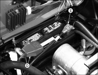
5. Connect Black negative (-) cable (E) to battery. Apply petroleum jelly or silicone spray to terminal to prevent corrosion. Make sure connection is tight.
· If the voltage is below 11.6 Volts, charge the battery. (See Charging the Battery in the
Service-Electrical section).
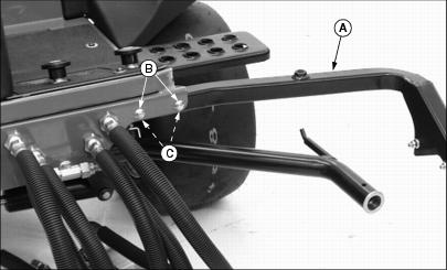
Install Left Yoke Stop Arm
· Attach yoke stop arm (A) to greens mower foot platform with two M8 x 50 carriage bolts (B) and two M8 flanged hex lock nuts (C).
Check Engine Oil Level

Picture Note: Top photo shows engine compartment in liquid cooled gas model greens mower.
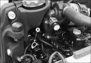
Picture Note: Bottom photo shows engine compartment in diesel model greens mower.
2. Remove oil dipstick (A). Wipe it clean.
4. Remove dipstick and check oil level. Oil must be between ADD and FULL marks on dipstick.
Checking Hydraulic Oil Level
· Check oil level on sight glass (A). Oil should be maintained to a mid-level range (B) on the sight glass.
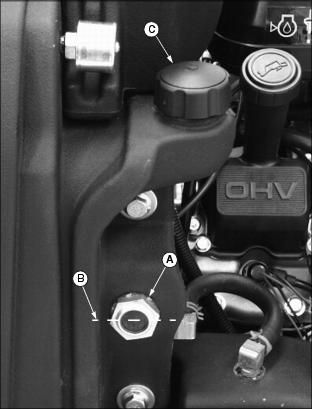
Picture Note: Engine area of liquid cooled gas model greensmower shown.
· Remove reservoir cap (C). Add oil at reservoir fill cap location until oil level reaches mid-level range on the sight glass. (See Transmission and Hydraulic Oil in this section for the proper oil application.)
4. Install and tighten reservoir cap.
Assemble Cutting Units
The Model 2500 Tri-Plex Greensmower is shipped from the factory without the cutting units installed. The hydraulic reel motors and cutting reel yokes are shipped with the greensmower.
Refer to installation instructions packaged with the cutting units when installing the cutting units and cutting unit yokes onto the greensmower. Retain these instructions with the operator's manual for future reference.
Hardware used to install the cutting units and cutting unit yokes onto the greensmower is included in the greensmower parts bag. Hardware must be retained for cutting unit and cutting unit yoke assembly procedures.
Check Tire Pressure
2. Check tire pressure with an accurate gauge.
Check Machine Safety Interlock System
Perform safety system check to make sure the electronic safety interlock circuit is functioning properly. (See Testing the Safety Interlock System in the Operating Machine section.)
Check and Adjust Lift Arm Stops
NOTE: Lift arm stop adjustment must be performed when changing tire sizes.
Before checking the lift arm stop adjustment:
· Reduce inflation pressure in all tires to 69-83 kPa (10-12 psi). Tires are shipped over inflated.
· Install all three cutting units.
Check Adjustment
1. Turn key switch to the RUN position.
2. Push Raise/Lower lever FORWARD to relieve hydraulic pressure in the front and center lift arm cylinders.
3. Push down front and center lift arms.

4. Turn key switch to the STOP position.
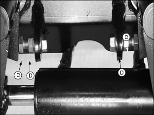
5. Measure distance (A) between the center of each yoke ball joint and the ground.
· All three yoke ball joints should be 225 5 mm (8.86 in. .20 in.) above the ground with the lift arm down stop plates (B) contacting the stop bolts (C).

Picture Note: Bottom left photo shows the front cutting unit lift arm down stop plates contacting the down stop bolts. Bottom right photo shows the center cutting unit lift arm down stop plate contacting the down stop bolt.
Adjust Lift Arm Stops
1. Loosen stop bolt jam nuts (D).
Picture Note: Top photo shows front cutting unit lift arm stop adjustments.
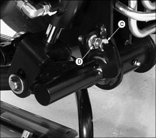
Picture Note: Bottom photo shows center cutting unit lift arm stop adjustment.
2. Measure distance (A) between the center of each yoke ball joint and the ground.
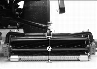
· Adjust the stop bolts (C) as needed until all three yoke ball joints are 225 5 mm (8.86 in. .20 in.) above the ground.