![]()
Introduction
Safety Signs
Controls
Operating Machine
Operating Cutting Units
Replacement Parts
Service Machine Safely
Service Interval Chart
Service Lubrication
Service Engine Gas Units
Service Engine Diesel Units
Service Hydraulics & Transmission
Service Cutting Units
Service Electrical
Cleaning and Replacing Battery
Checking Battery Electrolyte Level
Replacing Engine Indicator Light Bulb
Service Miscellaneous
Troubleshooting
Storing Machine
Assembly
Specifications
Warranty
John Deere Service Literature
John Deere Quality Statement
Copyright© Deere & Company

Service Electrical
Cleaning and Replacing Battery
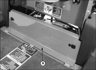
1. Raise and secure operator seat in the raised position.
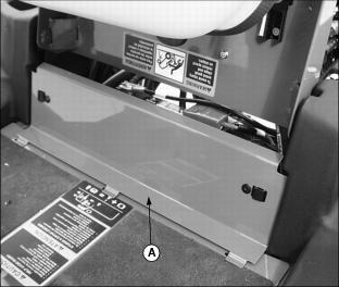
2. Remove service access panel (A) below operator seat platform.
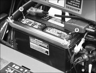
3. Loosen wing nuts (B) to remove battery hold-down (C).
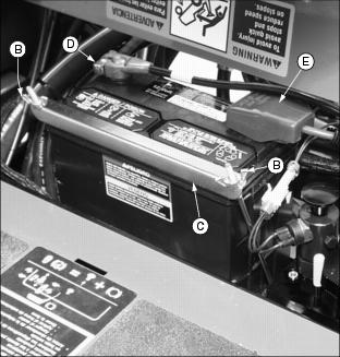
4. Remove negative (black) cable (D) from battery first.
5. Remove positive (red) cable (E).
6. If battery is very dirty, remove battery through access panel opening.
7. Clean battery, battery terminals, cable ends, hold-down cover, battery box, and other parts with a solution of 1 part baking soda to 4 parts water. KEEP solution out of battery cells.
8. Rinse all parts with clean water. Let dry.
10. Check cell caps to be sure vent holes are open.
11. Connect positive (red) cable to battery first, then negative (black) cable.
12. Apply petroleum jelly on battery terminals to help prevent corrosion.
13. Install battery hold-down. Tighten wing nuts.
14. Install service access panel.
Checking Battery Electrolyte Level
NOTE: Under normal operating conditions the battery should require no maintenance.
1. Raise and secure operator seat in the raised position.
2. Remove service access panel (A) below operator seat platform.
3. Remove battery manifold caps (B).
IMPORTANT: Avoid damage! DO NOT fill cells to the bottom of the filler neck (C). Electrolyte can overflow when battery is charged and cause damage. |
4. Electrolyte (D) should be 6 mm (1/4 in.) above plates (E).
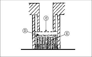
5. Add distilled water if necessary.
7. Install service access panel.
Charging the Battery
Follow instructions on the battery charger or in the charger operator's manual, or use the instructions below as a guide.

BEFORE CHARGING A BATTERY:
· Wait until the battery has warmed to room temperature. Do not charge a frozen battery.
· Check the electrolyte level of each cell. (See Checking Battery Electrolyte Level in this section.)
· Install the battery cap(s) on the battery.
Turn OFF and unplug the charger before you connect cables to the battery or disconnect cables from the battery.
If the battery becomes warm to touch during charging:
· Stop charging the battery until it cools.
KEEPING BATTERY FULLY CHARGED:
1. Remove and clean battery. (See Cleaning Or Replacing Battery in this section.)
2. Check electrolyte level. (See Checking Battery Electrolyte Level in this section.)
3. Leave cell caps on battery while you charge it.
4. Connect positive (+) charger cable to positive (+) battery terminal.
5. Connect negative (-) charger cable to negative (-) battery terminal.
7. Charge battery. (See Charging Rates in this section.)
8. Unplug charger cord. Remove charger cables.
Charging Rates
See your battery charger or charger operator's manual for information on charging. Or read the information below to FULLY CHARGE your battery.
For a charger with a CURRENT ADJUSTMENT CONTROL:
· Adjust the control to 10 amps.
· Charge the battery for 6-8 hours.
For a charger with a switch for MAINTENANCE FREE, DEEP CYCLE, or NORMAL (CONVENTIONAL) setting:
· Use the MAINTENANCE FREE or DEEP CYCLE setting.
For a charger with SLOW CHARGE, FAST CHARGE, or BOOST CHARGE setting:
· DO NOT use the BOOST CHARGE setting.
· Use the SLOW CHARGE setting:
· - For a charger rated at less than 10 amps.
· Use the FAST CHARGE setting:
· - For a charger rated at 10 amps.
NOTE: Your charger may have an AUTOMATIC STOP to prevent charging the battery:
· When the battery is fully charged OR
· When the battery is not in condition to take a charge.
Using Booster Battery

1. Connect positive (+) booster cable to booster battery positive (+) post (D).

2. Connect the other end of positive (+) booster cable to vehicle battery positive (+) post (A).
3. Connect negative (-) booster cable to booster battery negative (-) post (C).
4. Connect the other end of negative (-) booster cable (B) to engine ground away from battery.
Check Electrical Control Box
The electrical control box is a diagnostic tool to help the operator verify correct electrical functions of the greensmower. For the control box to control the greensmower as desired, each of the input switches, output solenoids and relays must be connected and functioning properly.
· Raise and secure operator seat in the raised position.
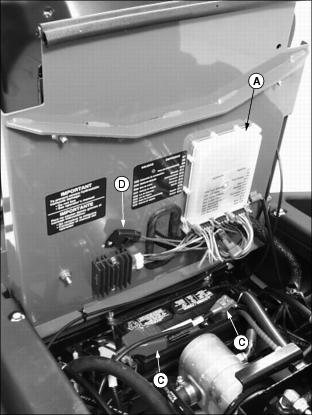
· Locate electrical control box (A).
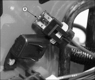
· The control box is equipped with a diagnostic light which indicates if the control box is functioning correctly. When the control box is functioning correctly, the diagnostic "HEARTBEAT" light (B) will be illuminated and blinking whenever the key switch is turned to the RUN position.
NOTE: DO NOT remove control box from position under operator seat platform if "HEARTBEAT" light fails to operate.
· If the "HEARTBEAT" light is not illuminated and blinking when the key switch is turned to the RUN position, this may indicate that the control box is without power or not functioning correctly.
· Check to see if battery is charged. Charge as needed. (See Charging the Battery in this section.)
· Battery connections (C). (See Cleaning and Replacing Battery in this section.)
· Blown 15 amp key switch fuse (D). (See Checking and Replacing Fuse in this section.)
· Control box display lights (E) will light as each function switch is actuated. If a function is performed and no display light appears, diagnose the problem.

· If further diagnostic assistance is needed, refer to the Technical Manual or consult your local John Deere dealer.
Checking and Replacing Fuse
IMPORTANT: Avoid damage! Help prevent greens mower electrical circuit damage. Make sure replacement fuse is the correct 15 amp size. |
1. Park greensmower on a hard, level surface.
2. Stop engine and engage park brake.
3. Raise and secure operator seat in the raised position.

4. Locate fuse holder (A) under operator seat platform.
· Check fuse (B) visually for a broken filament.
Replacing Engine Indicator Light Bulb
1. Park greensmower on a hard, level surface.
2. Stop engine and engage park brake.
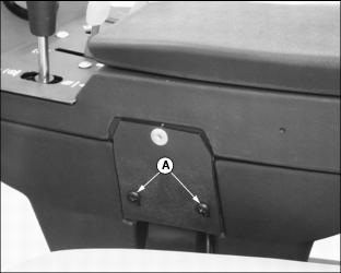
3. Remove two screws (A) from left side of console control armrest.

4. Raise and secure operator seat in the raised position.
5. Loosen and remove cap screws and flat washers from locations (B) in bottom of console control armrest.
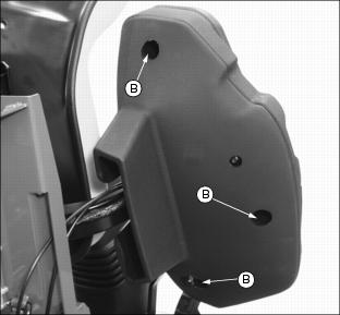
6. Carefully separate upper and lower console control armrest halves.
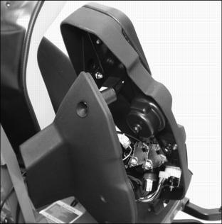
7. Locate engine indicator light assembly (C).
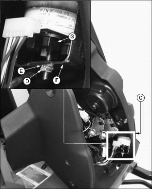
NOTE: It may be necessary to remove hex nut (D), lock washer (E) and retainer bracket (F) to access all engine indicator light bulb sockets.
· Turn light socket (G) counterclockwise to remove from assembly.
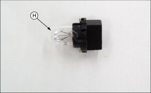
· Remove bulb (H) from socket.
· Install socket and turn clockwise to secure in position.
9. Carefully assemble upper and lower console control armrest halves.
· Install cap screws and flat washers into bottom of console control armrest locations (B). Do Not tighten.

· Install two screws (A) into left side of console control armrest.