![]()
Introduction
Safety Signs
Controls
Operating Machine
Rotating Blades are Dangerous - Protect Children and Prevent Accidents
Using Fuel Shut-Off Valve (Diesel Model)
Using Sit-On-Seat (SOS) Indicator Light Diagnostics
Emergency Stopping-Greensmower
Using Hydrostatic Transmission
Avoid Damage to Plastic and Painted Surfaces
Operating Cutting Units
Replacement Parts
Service Machine Safely
Service Interval
Service Lubrication
Service Engine Gas Units
Service Engine Diesel Units
Service Hydraulics & Transmission
Service Cutting Units
Service Electrical
Service Miscellaneous
Troubleshooting
Storing Machine
Assembly
Specifications
Warranty
John Deere Service Literature
John Deere Quality Statement
Copyright© Deere & Company

Operating Machine
Operate Safely

· Check brake action before you operate. Adjust or service brakes as necessary.
· Inspect machine before you operate. Be sure hardware is tight. Repair or replace damaged, badly worn, or missing parts. Be sure guards and shields are in good condition and fastened in place. Make any necessary adjustments before you operate.
· Clear work area of objects that might be thrown. Keep people and pets out of the work area. Stop machine if anyone enters the area.
· If you hit an object, stop the machine and inspect it. Make repairs before you operate. Keep machine and attachments properly maintained and in good working order.
· DO NOT leave machine unattended when it is running.
· Only operate during daylight or with good artificial light.
· Be careful of traffic when operating near or crossing roadways.
· Do not wear radio or music headphones while operating the machine. Safe operation requires your full attention.
Mount And Dismount Safely
· Do not step on pedals when mounting or
dismounting.
· Keep step area and platform clean.
· Stop machine, move Mow/Transport lever to transport position, lower cutting units to the ground, lock park brake, stop engine, remove key, and wait for all moving parts to stop before dismounting.
Park Safely
· Stop machine on a level surface, not on a slope.
· Move the Mow/Transport lever to the TRANSPORT ) position.
· Before you leave the operator's location, wait for engine and all moving parts to STOP.
Keep Riders Off
· Only allow the operator on the machine. Keep
riders off the machine.
· Riders on the machine may be struck by foreign
objects or thrown off the machine causing serious injury.
· Riders obstruct the operator's view resulting in the machine being operated in an unsafe manner.
Operator Training Required
· Study operation section of this manual before operating the machine.
· Operate machine in an open, unobstructed area under the direction of an experienced operator.
· Learn the use of all controls before operating on a green.
· Operator experience is required to learn the moving, stopping, turning and other operating characteristics of the machine.
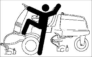
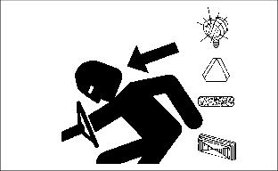
Rotating Blades are Dangerous - Protect Children and Prevent Accidents
· Never assume that children will remain where you last saw them. Children are attracted to mowing activity, stay alert to the presence of children.
· Keep children in the house when you are operating the machine.
· Turn machine off if a child enters the mowing area.
· Use extra care when you come to blind corners, shrubs, trees, or other objects that may block your vision.
· DO NOT let children or an untrained person operate the machine.
· DO NOT carry or let children ride on machine or any attachment. DO NOT tow children in a cart or trailer.
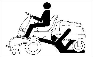
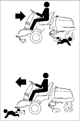
HELP PREVENT SERIOUS OR FATAL ACCIDENTS:
· Be alert at all times, drive forward carefully. People especially children can move quickly into the mowing area before you know it.
· Back carefully. Shut off cutting units and look behind the machine carefully, especially for children, before you back up.
· Shut off cutting units when you are not mowing.
· DO NOT operate machine if you are under the influence of drugs or alcohol.
Avoid Tipping
· DO NOT drive where machine could slip or tip.
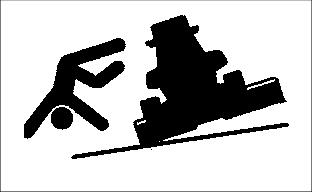
· Stay alert for holes and other hidden hazards in the terrain while driving to the work site.
· Slow down before you make a sharp turn or operate on a slope.
· MOW UP AND DOWN A HILL-NOT ACROSS. Use caution when changing direction on a slope.
Wear Appropriate Clothing
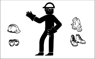
· Wear close fitting clothing and safety equipment appropriate for the job.
· Loud noise can cause impairment or loss of hearing, wear a suitable protective device such as earplugs.
· Do not wear radio or music headphones while servicing the machine. Safe service requires your full attention.
Check Wheel Bolts
· A serious accident could occur causing serious injury if wheel bolts are not tight.
· Check wheel bolt tightness often during the first 100 hours of operation.
Transport Safely
· Use safety lights and devices. Slow moving
machines when driven on public roads are hard
to see, especially at night. Avoid personal injury
or death resulting from a collision with a vehicle.
· Flashing warning lights are recommended whenever driving on public roads to increase visibility. Extra flashing warning lights may need to be installed.
Avoid Neutral Creep
· The machine may creep forward or backward while in neutral with engine running.
· After engine has started, release parking brake and with directional speed control speed pedals centered, machine should not move.
· If movement is evident, neutral return mechanism is adjusted incorrectly. (See Adjusting Transmission Neutral and Adjust Neutral Lock in the
Service-Hydraulics and Transmission section).
Avoid High Pressure Fluids
· Hydraulic hoses and lines can fail due to physical damage, kinks, age, and exposure. Check hoses and lines regularly. Replace damaged hoses and lines.
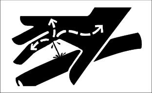
· Hydraulic fluid connections can loosen due to physical damage and vibration. Check connections regularly. Tighten loose connections.
· Escaping fluid under pressure can penetrate the skin causing serious injury. Avoid the hazard by relieving pressure before disconnecting hydraulic or other lines. Tighten all connections before applying pressure.
· Search for leaks with a piece of cardboard. Protect hands and body from high pressure fluids.
· If an accident occurs, see a doctor immediately. Any fluid injected into the skin must be surgically removed within a few hours or gangrene may result. Doctors unfamiliar with this type of injury should reference a knowledgeable medical source. Such information is available from Deere & Company Medical Department in Moline, Illinois, U.S.A. Information may be obtained in the United States and Canada only by calling
1-800-822-8262.
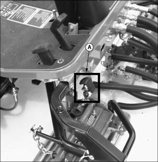
Adjusting Operator Seat

1. Sit on the operator's seat.
2. Pull and hold lever (A) to the left.
3. Slide seat forward or backward to desired position.
Adjusting Tilt Steering Wheel

Picture Note: Tilt steering wheel adjustment T-handle on diesel model shown.
1. Sit on the operator's seat.
2. Raise and hold adjustment T-handle (A).
3. Move steering wheel to desirable operating position.
4. Lower T-handle to lock steering wheel in position.
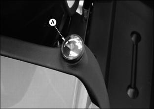
Using the Choke (Gas Model)
· Pull knob (A) out to CHOKE engine.
· Push knob (A) in to OPEN choke.
Using the Park Brake
Locking the Park Brake
1. Depress and hold brake pedal (A) down with right foot.
2. Depress park brake lock (B) with left foot.
4. Release park brake lock. Park brake pedal and park brake lock should remain locked in the down position.
NOTE: Forward and reverse travel pedals are not operational when park brake is locked.
Unlocking the Park Brake
1. Depress park brake pedal (A). Park brake lock (B) should release immediately.
Glow Plug (Diesel Model)
NOTE: Glow plugs preheat the combustion chamber for better starting performance.
1. Turn key switch to the RUN position.
· The amber glow plug indicator light (A) should go on.
· The indicator light should go off in approximately three seconds after the key switch is turned to the RUN position.
2. Turn the key switch to the START position.
· When the engine starts, release key switch to the RUN position.
Using the Raise/Lower Lever
Picture Note: Console controls on gas model shown.
1. Push Raise/Lower lever (A) forward to lower cutting reels.
· If the Mow/Transport lever (B) is in the MOW) position the cutting reels will begin to rotate.
· If the Mow/Transport lever is in the TRANSPORT )position, cutting units will lower but will not engage.
2. Pull lever (A) rearward to raise cutting units.
· If the Mow/Transport lever is in the MOW ) position cutting reel rotation will stop.
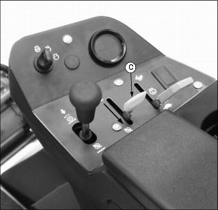
Using the Mow/Transport Lever

Picture Note: Console controls on gas model shown.
1. Pull the Raise/Lower lever (A) rearward to raise cutting units.
2. Move the Mow/Transport lever (B) to the MOW ) position.
3. Push the Raise/Lower lever forward to lower cutting units.
· Cutting reels will begin to rotate when the cutting units are lowered.
4. Pull Raise/Lower lever rearward to raise cutting units.
· Cutting reels will stop rotating when the cutting units are raised.
5. Move the Mow/Transport lever to the TRANSPORT ) position to disengage reel drive for cutting units.
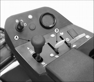
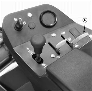
Using the Throttle Lever

Picture Note: Console controls on gas model shown.
· Push throttle lever (A) all the way forward to the FAST (r) position when mowing.
· Move lever (A) to the half throttle (R) position when starting and warming the engine.
· Pull lever (A) all the way rearward to the SLOW (t) position. Do not run engine at SLOW (t) idle any longer than necessary.
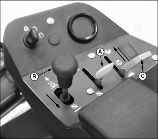
Using the Key Switch
NOTE: To help prevent engine backfiring, the engine will continue to run approximately two seconds after keyswitch is turned to the "STOP" position. After engine has stopped, an approximate two-second delay will prevent the engine from immediately being restarted.
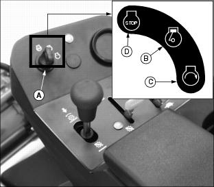
Picture Note: Console controls on gas model shown.
· Turn key switch (A) to the RUN position (B). The engine oil pressure indicator light and battery indicator light should come on. Engine is ready to start.
· Turn key switch to the START position (C) to start engine.
· Turn key switch to the STOP position (D) to stop engine.
Using the Fuel Gauge
· Fuel gauge (A) indicates fuel level.
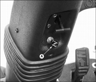
Using Fuel Shut-Off Valve (Diesel Model)
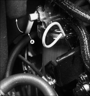
Picture Note: Fuel shut-off valve shown in the open position.
2. Locate fuel filter sediment bowl assembly on the left side of the engine.
3. Rotate two position fuel shut-off valve lever (A) to the "O" (open) position or "C" (closed) position.
"C" (Closed) position:
· When performing any type of engine service.
· During periods of extended storage.
"O" (Open) position:
· Fuel shut-off valve must be in the full OPEN position for proper fuel delivery to the engine.
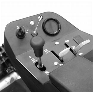
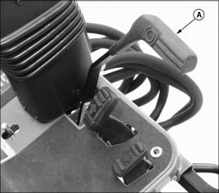
Using the Hour Meter
NOTE: Hour meter will continue to run when key switch is left in the RUN position.
· Open hinged console control armrest (A) to locate hour meter.
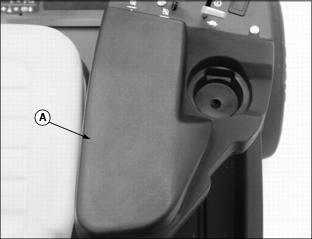
· The hour meter (B) shows the approximate number of hours the greensmower has run.

· The service interval chart provides information on necessary service intervals. Use the hour meter and Service Interval Chart to determine when the greensmower will need service. (See Service Interval Chart.)
Indicator Lights

Picture Note: Console controls on diesel model shown.
· When the key switch is turned to the RUN position, the battery discharge indicator light (C) and the engine oil pressure indicator light (B) should come on in light assembly module.
· When the key switch is turned to the START position, the hydraulic oil temperature indicator light (A), the engine oil pressure indicator light (B), the battery discharge indicator light (C) and the engine coolant temperature indicator light (D) should all come on in the light assembly module.
· After the engine starts, all four indicator lights should go out.
· If any or all indicator lights remain lit after engine has been started, stop engine immediately. Diagnose and correct problem.
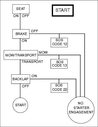
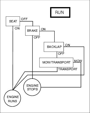
Using Sit-On-Seat (SOS) Indicator Light Diagnostics

NOTE: Sit-on-seat diagnostic code label is located under hinged console control armrest (A).
To energize the starter solenoid and engage the starter motor the following conditions must be met:
· Key switch must be turned to the START position.
· Park brake must be depressed which mechanically neutralizes the transmission linkage.
· The Mow/Transport lever must be in the TRANSPORT position (x).
· Backlap valve cannot be in the backlap position.
If one or more of these conditions is not met, the greensmower engine will not start.
"SOS" or Sit-On-Seat indicator light diagnostics are provided to assist the operator in getting the greensmower started.
· Turn and hold key switch in the START position.
· If engine does not crank, the oil pressure indicator light should remain lit and the battery discharge light will begin to flash.
· The PARK BRAKE light pattern is one flash, a short pause and two additional flashes. This flash code sequence indicates that the park brake switch has not been activated. Engage park brake to start engine.
· The MOW SWITCH light pattern is one flash, a short pause and three additional flashes. This flash code sequence indicates that the mow switch is activated. Move Mow/Transport lever to the TRANSPORT position (x) to start engine.
· The BACKLAP SWITCH light pattern is two flashes, a short pause and two additional flashes. This flash code sequence indicates that the backlap valve is in the backlap position. Turn off backlap valve and start engine.
(See Starting the Engine in this section and Backlapping Cutting Units in the Service-Cutting Units section.)
Ignition Interlock Systems
For the starter to engage, the following conditions must be met:
· Operator can be on or off the seat.
· Mow/Transport lever in the TRANSPORT )position.
For the engine to run, the following condition must be met:
· Operator must be on the seat or the park brake must be engaged.
If the Mow/Transport lever is in the TRANSPORT ) position with the park brake not engaged and the operator raises off the seat, the engine will stop.
If the Mow/Transport lever is in the MOW ) position with the park brake engaged and the operator raises off the seat, the engine will stop.
If the operator is mowing and raises off the seat, the cutting reels and engine will stop.
· In order to mow, the following conditions must be met:
· Operator in the operator seat.
· Throttle lever moved to the FAST ) position.
· Mow/Transport lever in the MOW) position.
· Cutting units lowered to the ground.
If the operator is mowing and the park brake is depressed, the cutting reels will stop rotating.
If the operator is mowing and engages the backlapping valve while on the operator seat, the cutting reels will stop rotating.
If the operator attempts to backlap the cutting units with the operator seat occupied, the cutting reels will not rotate.
If the operator is backlapping the cutting units with the operator seat not occupied and the park brake is disengaged, the engine will stop.
Starting the Engine
2. Adjust operator seat to most comfortable position. (See Adjusting Operator Seat in this section.)
NOTE: Greensmower has an ignition interlock switch. Engine will not start unless the park brake is engaged and the Mow/Transport lever is in the TRANSPORT )position.

4. Put Mow/Transport lever (C) in the TRANSPORT )position.
Picture Note: Console controls on gas model shown.
5. Move throttle lever (D) to the half speed position (R).
Picture Note: Console controls on gas model shown.
· Cold engine: Pull knob out to the CHOKE (k) position.
· Warm/hot engine: If necessary, pull knob out to the CHOKE (k) position.
7. Turn key switch to the RUN position (F).
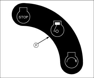
8. Check that both engine indicator lights go on.


· After approximately three seconds indicator light will go off. Engine is now ready to start.
10. Turn key switch to the start position (J).
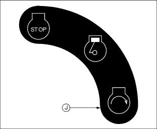
11. When engine starts, release key to the RUN position.
12. Move throttle lever to HALF SPEED position ).
Warming and Idling Engine
Warming Engine:
· Run engine at the half throttle speed position (R)
for 2-3 minutes.
Idling Engine:
· The engine needs a large volume of air to keep cool. Keep grill screen, oil cooler coils and radiator cooling fins clean. DO NOT idle engine for long periods of time.
Stopping Engine

Picture Note: Console controls on gas model shown.
1. Move throttle lever (A) to SLOW ) position. Let engine idle before stopping.
2. Move Mow/Transport lever (B) to the TRANSPORT) position.
3. Push raise/lower lever (C) forward to lower cutting reels. Wait until the center cutting reel is fully lowered.
4. Lock the park brake. (See Using the Park Brake in this section.)
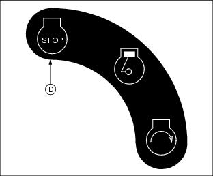
NOTE: To help prevent engine backfiring, the engine will continue to run approximately two seconds after keyswitch is turned to the "STOP" position. After engine has stopped, an approximate two second delay will prevent the engine from immediately being restarted.
5. Turn key switch to "STOP" position (D).
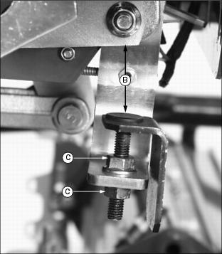
Adjust Mowing Speed
NOTE: Greensmower is preset at the factory to operate at approximately 7.1 km/h (4.4 mph).
Wheel RPM's necessary to meet the preset mow speed specification are 18012. Wheel RPM's have been preset at the factory to assure proper forward mow speed regardless of tire size.
1. Park greensmower on a hard, level surface.
2. Stop engine and engage park brake.
3. Locate mow speed adjustment (A).
4. Move Mow/Transport lever to the MOW (X) position.
NOTE: Preliminary dimension (B) between top of mow speed adjustment and bottom of forward travel pedal linkage is 22 mm (.87 in.)
When mow speed adjustments change, record any dimension (B) changes for future reference.
· Turn threaded adjustment down for increased mowing speed.
· Turn threaded adjustment up for decreased mowing speed.
7. Move Mow/Transport lever to the TRANSPORT ) position.
8. Measure off 30.5 m (100 ft.)
10. Move Mow/Transport lever to the MOW ) position.
11. Move throttle lever to the FAST ) position. Depress FORWARD travel pedal fully.
· Record the number of seconds it takes to travel the 30.5 m (100 ft.) length.
· Refer to applicable cutting ratio table to determine ground speed and frequency of cut.
12. Continue adjustment process until desired mowing speed and frequency of cut is achieved.
Cutting Ratios
Emergency Stopping-Greensmower
· Push hard on park brake pedal (A).
Using Hydrostatic Transmission
Picture Note: Console controls on gas model shown.
2. Move Mow/Transport lever (A) to the TRANSPORT )position.
NOTE: Front cutting units will cycle into the raised position before the center cutting unit.
3. Pull Raise/Lower lever (B) rearward to raise cutting reels.
4. Move throttle lever (C) all the way forward to the FAST ) position.
To Travel Forward:

· Slowly depress speed control pedal (D) down to travel forward. The farther the pedal is pushed down the faster the mower will travel.
· Remove foot from pedal, pedal will return to the NEUTRAL position and greensmower will stop.
· Forward travel speed range is 0-13.7km/h
(0-8.5 mph).
To Travel In Reverse:
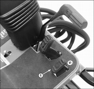
· Allow speed control pedal (D) to slowly return to the NEUTRAL position to stop forward travel.
· Slowly depress speed control pedal (E) down to travel in reverse. The farther the pedal is pushed down, the faster the mower will travel.
· Remove foot from pedal, pedal will return to the NEUTRAL position and greensmower will stop.
· Reverse travel speed range is 0-4.8km/h
(0-3 mph).
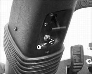
Using Free-Wheeling Tow Valve
IMPORTANT: Avoid damage! To prevent hydrostatic damage, NEVER tow the greensmower. Push or pull greensmower by hand only. Do not use another vehicle to push or pull greensmower. |
When movement of greensmower is required without starting the engine, use the free-wheeling tow valve.
2. Lift and secure operator seat in the raised position. (See Raising and Lowering Operator Seat in the Service-Engine section.)
3. Turn free-wheeling tow valve (A) counterclockwise approximately two revolutions.
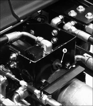
6. Push greensmower to desired location.
NOTE: Before starting engine, turn free-wheeling tow valve clockwise to the operating position.
Daily Operating Checklist
Testing Safety Systems
Use the following checkout procedure to check for normal operation of greensmower.
If there is a malfunction during one of these procedures, DO NOT operate greensmower. (See your John Deere distributor for service.)
Perform these tests in a clear open area. Keep bystanders away.
Test 1

3. Hydrostatic travel pedals in a NEUTRAL position.
4. Move Mow/Transport lever to the MOW (X) position.
5. Turn key switch to the START position (A). Engine must not crank.
6. Turn key switch to the "STOP" position (B).
7. Move Mow/Transport lever to the TRANSPORT (x) position.
8. Turn key switch to the START position (A). Engine should crank.
Test 2
3. Hydrostatic travel pedals in a NEUTRAL position.
6. Lower cutting units to the ground.
7. Move Mow/Transport lever to the MOW (X) position.
8. Engine must stop in two seconds with no rotation of cutting reels.
Test 3
3. Move Mow/Transport lever to the TRANSPORT (x) position.
6. Hydrostatic travel pedals in a NEUTRAL position.
7. With engine running, move Mow/Transport lever to the MOW (X) position.
8. Push the Raise/Lower lever forward. Cutting reels should start rotating.
10. Engine must stop within two seconds.
Test 4
5. Hydrostatic travel pedals in a NEUTRAL position.
6. Move mow/transport lever to the TRANSPORT ) position.
7. With engine running at idle, raise off seat.
8. Engine must stop within two seconds.
Test 5
3. Move Mow/Transport lever to the TRANSPORT ) position.
6. Hydrostatic travel pedals in a NEUTRAL position.
7. Lower cutting units with the Raise/Lower lever.
8. Move Mow/Transport lever to the MOW (X) position.
9. Cutting reels must not rotate.
10. Raise and lower cutting units.
11. Cutting reels should begin to rotate.
Avoid Damage to Plastic and Painted Surfaces
· Insect repellent spray may damage plastic and painted surfaces. Do not spray insect repellent near machine.
· Be careful not to spill fuel on machine. Fuel may damage surface. Wipe up spilled fuel immediately.
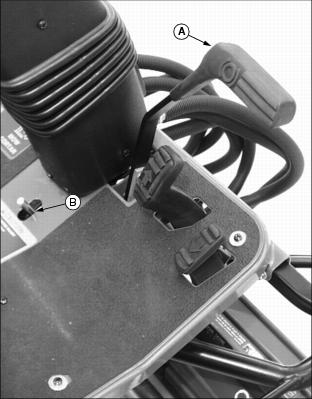
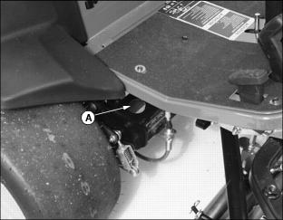
Transporting the Greensmower
IMPORTANT: Avoid damage! NEVER TOW the greensmower. Damage to hydrostatic pump and transaxle will occur if towed. |
· Use a heavy-duty trailer designed to carry 909 kg (2000 lb), or a truck box to transport the machine.
· If the machine is transported facing forward, the rear engine cowling should be secured to the machine at the front to avoid the hood opening accidentally during transporting.
· Lower the cutting units to the deck.
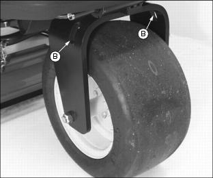
· Fasten machine with straps, chains, or cables.
· The tie downs should be attached to slots (A) provided on both sides of the operator's station in the main frame and slots (B) on both sides of the rear wheel yoke.
· When transporting the machine on a road or highway, use accessory lights and devices for adequate warning to operators of other vehicles. Check local, state, provincial, or federal laws.