![]()
Introduction
Safety Signs
Controls
Operating Machine
Operating Cutting Units
Avoid Injury From Contacting Blades
Adjust Front Roller Parallel with Bed Knife
Adjust Cutting Unit Lift Height
Operating (Optional) Greens and Turf Conditioner
Adjusting (Optional) Greens and Turf Conditioner
Adjusting (Optional) Rear Roller Powered Brush
Operating and Adjusting (Optional) Vertical Cutters
Emergency Stopping-Cutting Reels
Removing and Emptying Grasscatchers
Replacement Parts
Service Machine Safely
Service Interval
Service Lubrication
Service Engine Gas Units
Service Engine Diesel Units
Service Hydraulics & Transmission
Service Cutting Units
Service Electrical
Service Miscellaneous
Troubleshooting
Storing Machine
Assembly
Specifications
Warranty
John Deere Service Literature
John Deere Quality Statement
Copyright© Deere & Company

Operating Cutting Units
Check Ground Conditions
· Clear mowing area of objects that might be thrown.
Keep people and pets out of mowing
area.
· Study mowing area. Set up safe mowing pattern.
Do not mow under conditions where traction or stability is doubtful.
· First, test drive area with CUTTING UNITS OFF but lowered. Slow down when you travel over rough ground.
Avoid Injury From Contacting Blades
BEFORE YOU DISMOUNT TO UNPLUG OR
ADJUST CUTTING UNITS:
· DISENGAGE reel drive by moving the mow/transport
lever to the TRANSPORT position.
· LOWER the cutting units to the ground.
· Wait for reels and all moving parts to STOP.
BLOCKED OR STALLED CUTTING CYLINDERS:
· Keep all parts of the body away from the cutting edges. Residual hydraulic pressure in the system can cause cutting cylinder rotation when the blockage is released.
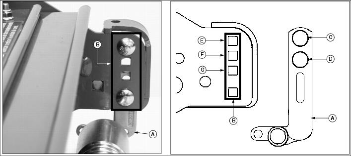
Adjust Bed Knife-to-Reel
IMPORTANT: Avoid damage! When adjusting bed knife-to-reel, lower and raise the bed knife evenly. DO NOT adjust more than one flat on the adjuster nut at a time, alternating side to side. |
1. Remove cutting reels from greensmower. (See Removing and Installing Cutting Units in the Service-Cutting Units section.)
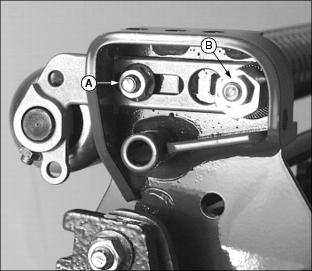
2. Position cutting unit upright on workbench as shown.
3. On both sides of cutting unit, loosen jam nut (A) and turn bed knife tower adjuster (B) counterclockwise until bed knife (C) is tight against cutting reel (D).

4. Slowly tighten tower adjuster (B) clockwise, alternating from side to side until bed knife begins to pull away from the cutting reel. Cutting reel should rotate freely.
NOTE: Make sure that the final adjustment to the bed knife is pulling the bed knife away from the cutting reel.
5. With the use of a feeler gauge, alternately turn adjusters (B) no more than one flat at a time until bed knife to reel clearance (E) measures .025 mm to .050 mm (.001 in. to .002 in.).
6. Tighten jam nuts (A). Check the bed knife-to-reel clearance (E). Adjust again if necessary.
Adjust Height Of Cut Range
Adjust front roller brackets for the height of cut (HOC) range desired.
· Select height-of-cut (HOC) adjustment range by adjusting the position of both front roller brackets.
· Alignment of roller bracket (A) and cutting unit frame adjustment holes (B) on each side of the cutting unit will determine the HOC adjustment range.
· Refer to chart for desired setting.
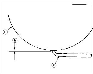
Adjust Front Roller Parallel with Bed Knife
NOTE: Use of a bench plate or a two or three bolt height-of-cut gauge bar is recommended when adjusting front roller parallel with the bed knife.
Always adjust bed knife-to-reel before adjusting front roller for parallelism.
Always make parallelism adjustment after adjusting front roller height of cut range.
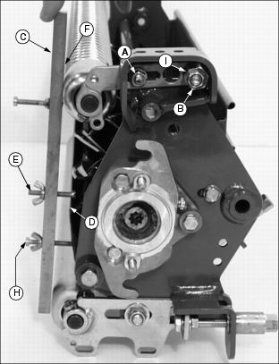
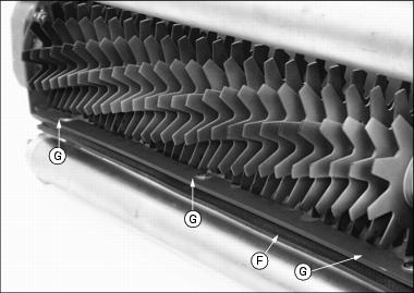
Parallelism Adjustment with Bench Plate
1. Position cutting unit upright on flat surface or workbench.
2. Loosen hex nut (A) and hex nut (B) on the left roller bracket.

3. Set bench plate on a level surface. Set cutting unit on top of bench plate (C). Bed knife (D) must rest firmly against plate stop (E) with cutting reel blade (F) on top of plate stop.
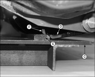
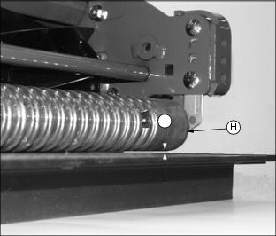
4. Rotate eccentric adjuster (G) until the front roller (H) sits flat and parallel with the bench plate. Gap (I) should not exceed .050 mm (.002 in.) maximum.

5. Tighten left roller bracket hex nut (A).
6. Tighten left roller bracket hex lock nut (B).
Parallelism Adjustment with HOC Gauge Bar
1. Position cutting unit upright on flat surface or workbench.
2. Loosen hex nut (A) and hex nut (B) on the left roller bracket.
NOTE: HOC gauge bar should not contact the bottom of the rear roller.
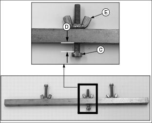
3. Rest HOC gauge bar (C) approximately 51 mm
(2 in.) from the RIGHT end of the bed knife (D).
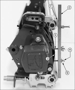
4. Hook the center gauge screw (E) on the edge of the bed knife. Hold end of gauge bar against the bottom of front roller (F).
5. Loosen wing nut (G). Turn lower gauge screw (H) clockwise until top of screw makes contact with flat edge of bed knife.
NOTE: HOC gauge bar should not contact the bottom of the rear roller.
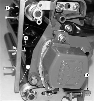
7. Rest HOC gauge bar (C) approximately 51 mm
(2 in.) from the LEFT end of the bed knife (D).
8. Hook the center gauge screw (E) on the edge of the bed knife. Hold end of gauge bar against the bottom of front roller (F).
9. Adjust position of front roller.
· Rotate eccentric adjuster (I) until top of lower gauge screw (H) makes contact with the bed knife.
10. Tighten left roller bracket hex nut (A).
11. Tighten left roller bracket hex lock nut (B).
12. Check adjustment using HOC gauge bar.
Adjust Height of Cut
1. Position cutting unit upright resting on the rear roller brackets.
2. On both sides of rear roller, loosen lock nut (A) just enough for the height-of-cut (HOC) bracket (B) to slide.

NOTE: If greensmower is equipped with the optional rear roller powered brush, the idler gear pivot lock nut and pivot bracket lock nuts must be loosened. (See Adjusting (Optional) Rear Roller Powered Brush in this section.)
3. On the height-of-cut (HOC) gauge bar, set center adjustment bolt head (C) at the desired height of cut (D). Lock wing nut (E).
4. Rest HOC gauge bar against front roller (F) approximately 51 mm (2 in.) from the end of the bed knife. Set the inside of the bolt head (G) against the edge of the bed knife.
5. Turn tower adjuster (H) until the rear roller (I) contacts the HOC gauge bar. Repeat for the other side of the cutting reel.
6. Check HOC adjustment setting from side to side and adjust if necessary. Tighten lock nut (A) on both sides of cutting unit.
Adjust Cutting Unit Lift Height
NOTE: All cutting unit lift chains must be adjusted equally.
The cutting unit lift chains (A) can be adjusted if a different cutting unit lift height is desired.
· For initial set up, attach the seventh chain link to each cutting unit lift arm pin (B). Most normal mowing applications will use the seven chain link set up.
· For applications with level greens and wanting more ground clearance for cutting unit transport, use a six chain link or less set up. This set up will restrict float on greens with extreme undulations and contours.
· For applications with extreme undulations and contours on greens, use a eight or nine chain link set up. Cutting unit ground clearance will be limited for transport.
Adjust Reel Speed
IMPORTANT: Avoid damage! It recommended to use the highest speed necessary to avoid marcelling. Reduced reel speed may help reduce bed knife and reel wear. |
1. Park greensmower on a hard, level surface.
2. Stop engine and engage park brake.
3. Open service access panel (A) below operator seat platform.
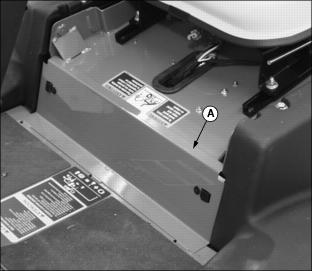
4. Locate reel speed control knob (B) behind service access panel.
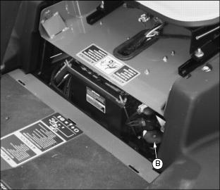
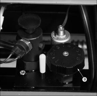
· Reel speed can be adjusted depending on the type of application for the greensmower, which type of cutting units are used, and grass height and conditions.
· It may be appropriate to reduce reel speed when cutting taller grass to prevent grass from being blown over and not being cut. Faster reel speeds with dry grass may cause grass clippings to be thrown over the grasscatcher.
(fully counterclockwise) for best cutting performance.
6. Close service access panel.
Operating (Optional) Greens and Turf Conditioner
IMPORTANT: Avoid damage! Help prevent dulling of blades. DO NOT use Greens and Turf Conditioner (GTC) for three days following top dressing. |
The conditioner process involves shallow vertical cutting. The blades are adjusted to cut runners and lift horizontal leaf material. It is important that frequent and thorough observations be performed or stress to the plants may occur. Make adjustments as necessary.
IMPORTANT: Avoid damage! The initial setting should be the same as Height Of Cut to prevent damage to the turf.
For a deeper cut, set approximately 0.79 mm |
NOTE: It is normal for grass catchers to fill faster when conditioning.
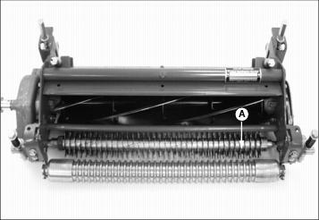
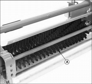
Picture Note: Cutting unit shown with seven blade cutting reel and attached conditioner reel (A).
1. Condition greens the first time with blades set the same as Height of Cut. (See Adjust Height Of Cut in this section). Closely examine each green and note any inconsistencies or appearance of over-aggressiveness. Decrease GTC penetration if necessary.
2. Check each green 1-2 hours after cutting. Look for any tendency toward a yellow or brown tint. This indicates over-stress.
3. If visible stress is observed, decrease GTC penetration to 0.39 mm (.016 in.).
4. Continue cutting/conditioning at this setting for three to five days. Check frequently for stress.
5. If no stress is observed, increase GTC penetration by 0.25 mm (0.010 in.). Check for obvious over-aggressiveness. Observe for two to three days, watching for signs of stress.
6. Repeat Step 5, until stress becomes visible. Back off the GTC adjusted penetration by 0.25 mm (0.010 in.).
NOTE: Stress is a cumulative result of many factors such as irrigation, temperature, humidity, chemical application, disease, thatch, etc.
Conditioning aggressiveness will require adjustment and monitoring as these factors vary.
Conditioning frequency may also need to be reduced in some cases.
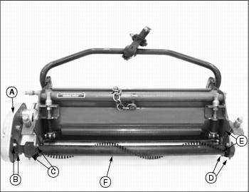
Adjusting (Optional) Greens and Turf Conditioner
NOTE: Height Of Cut must be adjusted prior to adjusting the Greens and Turf Conditioner.
· Press down on GTC adjuster bolts (A).
· Swing adjuster stops (B) around toward the front of the cutting unit.
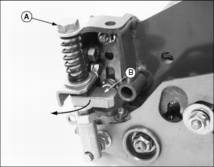
Picture Note: Top photo shows GTC adjuster stop disengaged and out of the operating position.
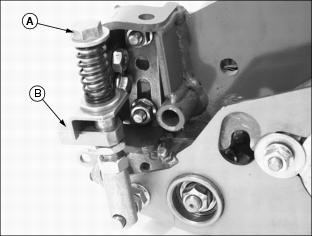
Picture Note: Bottom photo shows GTC adjuster stop engaged in the operating position.
2. Position cutting unit for making height of cut adjustment. (See Adjusting Height Of Cut in this section).
3. Set GTC adjustment screw (C) on the gauge bar to the desired operating height. (See Operating (Optional) Greens and Turf Conditioner in this section).
· Adjustment screw (D) may need to be loosened so that the gauge bar can rest on both the front and rear rollers.

4. Place preset gauge bar on cutting unit. Hook height of cut screw (E) on bed knife. The ends should rest firmly on the front and rear rollers.
5. Loosen adjuster lock nut (F) on both ends of the cutting unit.

6. Turn adjuster bolt (A) to raise or lower GTC roll. Alternate from end to end until the teeth touch the screw on the gauge bar. Tighten adjuster lock nuts.
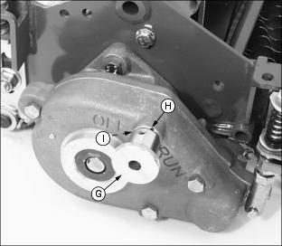
· Pull knob (G). Turn knob clockwise to the "RUN" position. Knob must engage detent (H).
· Turn knob counterclockwise to the "OFF" position. Knob must engage detent (I).
10. Disengage GTC adjuster stops.

· Press down on GTC adjuster bolts (A).
· Swing adjuster stops (B) around toward the rear of the cutting unit.
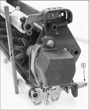
Adjusting (Optional) Rear Roller Powered Brush
NOTE: It is not necessary to remove the brush cover to adjust the powered brush.
1. Loosen idler gear pivot lock nut (A).
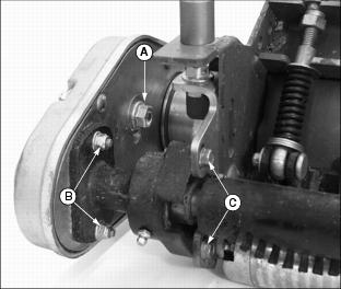
2. Loosen both pivot bracket lock nuts (B).
3. Loosen two flange head cap screws (C) on left side of cutting unit.
4. Loosen two flange head cap screws (D) and nylock nuts (E) on right side of cutting unit.
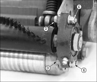
NOTE: The brush bristles should just barely clear the full length of the roller. The gap between the brush bristle tips and the roller should be approximately 1 mm (1/32 in.).
5. Slide the rear roller powered brush (F) up or down to adjust the roller.
6. Tighten flange head cap screws (C) on left side of cutting unit and flange head cap screws (D) and nylock nuts (E) on right side of cutting unit.
7. Tighten both pivot bracket lock nuts (B) and the idler gear pivot lock nut (A).
Operating and Adjusting (Optional) Vertical Cutters
NOTE: Vertical cutting units (A) are intended for thatch removal and should not be set for ground engagement. The cutters should not be set to penetrate the soil.
For excess thatch conditions, several trips across the green may be necessary. DO NOT attempt to remove large amounts of thatch in a single cutting.
· Adjust mow speed limit to no more than 4.8 km/h
(3 m.p.h.). The mow speed should be set properly to insure that the cutting reels do not stall out completely. (See Adjust Mowing Speed in the Operating Machine section.)
· Initial adjustment of blade depth should be flush with the bottom of the rollers. The depth can be increased as needed from this point to achieve desired results. Do not exceed a blade depth of 3 mm (.12 in.).
· Before making a vertical cutter adjustment, measure the usable blade length of the cutting blades. If usable blade length is less than the desired cutting depth, replace blades before continuing.
Adjusting Cutting Depth
1. Mark the desired cutting depth (B) on a gauge bar (C).
2. Place the gauge bar across the front and rear rollers approximately 50 mm (2 in.) in from the end of the rollers.
3. Loosen locknut (D) on each side of the cutting unit.
4. Adjust position of rear roller.
· Turn each tower adjuster (E) until leading edge of vertical cutting blade aligns with the cutting depth mark on the gauge bar.
· Rotate cutting reel back and forth to ensure blade tip does not extend beyond the depth mark.
· Check both ends of cutting reel until they are adjusted to the same setting.
· If the vertical cutter cannot be adjusted because of wear, replace the blades and then adjust to the correct depth.
NOTE: Adjustment of rubber flap height will depend on turf conditions.
· On short turf, lower the flap to prevent material from flying out the rear of the cutting unit.
· On turf with a lot of thatch, raise the flap to allow the removed thatch to exit out the rear of the cutting unit.
6. Adjust cutting unit rubber flap (F).
· Loosen three carriage bolts (G) and hex nuts.
· Adjust the flap approximately 13 mm (1/2 in.) up from the bottom of the rollers.
7. Repeat procedure for other cutting units.
Engaging Reel Drive
IMPORTANT: Avoid damage! Operate engine at full throttle so cutting units can operate at the correct speed. |
NOTE: The center cutting unit will raise and lower to the ground after the front cutting units.
1. Pull Raise/Lower lever (A) rearward to raise cutting units.
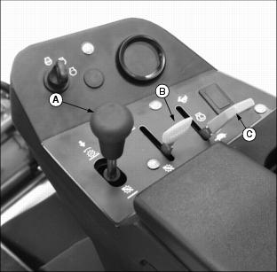
NOTE: If the cutting units are lowered to the ground before the Mow/Transport lever is moved to the MOW ) position, the cutting reels will not rotate.
Raise the cutting units, move the Mow/Transport lever to the MOW ) position. Lower cutting units to start reel rotation.
2. Move the Mow/Transport lever (B) forward to the MOW ) position.
3. Move the throttle lever (C) forward to the FAST ) position.
4. Slowly begin forward travel.
NOTE: The front cutting units lower to the ground before the center cutting unit.
Moving the Mow/Transport lever to the MOW ) position activates a switch so the cutting units automatically engage when lowered.
5. Push Raise/Lower lever forward to lower cutting units and start cutting reel rotation.
6. When the front cutting units reach the opposite edge of the green or fairway, pull back the Raise/Lower lever. The cutting units will raise to transport lift height and automatically turn off.
Emergency Stopping-Cutting Reels
· Cutting reel rotation will stop.
To begin cutting reel rotation:
· Raise and lower cutting units.
2. Move the Mow/Transport lever to the TRANSPORT ) position.
· Cutting reel rotation will stop.
To begin cutting reel rotation:
· Move the Mow/Transport lever to the Mow ) position.
· Raise and lower cutting units.
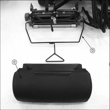
Removing and Emptying Grasscatchers
NOTE: Remove center grasscatcher from left side of greensmower.
1. Raise and remove link handle (A) from catcher bracket support hook (B).
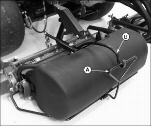
Picture Note: Top photo shows grasscatcher installed onto the frame assembly.

Picture Note: Bottom photo shows the link handle removed from the catcher bracket support hook with the grasscatcher ready for removal from the frame assembly.
2. Remove grasscatcher (C) from frame assembly (D) and empty.